|
Fred's Fusor
Vacuum |
|
Contents of this page
|
|||||||||||||||||||||||||||||||||||||||||||||||||||||||||||||||||||||||||||||||||||||||||||||||||||||||||||||||||||||||||||||||||||||||||||||||||||||||||
| Introduction The vacuum system consists of several components which make together the vacuum line. Main components are the vacuum chamber (also called the reactor), the foreline pump, the high vacuum pump and controlling equipment, e.g. the monitoring and measuring instruments. These components are connected to and with smaller vacuum components, e.g. tubing, valves, size reduction adapters, centering rings, o-rings, clamps, etc. The vacuum chamber will be described more in detail on the reactor page and a description of the monitoring and measuring instruments can be found on the monitors page. Main components in the Fusor vacuum system are the vacuum pumps, usually a roughing pump and a high vacuum pump. When considering to buy vacuum pumps for constructing a Fusor, different choices for types of pumps can be made in both categories roughing and high vacuum. Vacuum pumps can be categorized from noisy to quiet and from dirty to clean (see reference 1). The ultimate noisy and dirty vacuum pump is the rotary vane vacuum pump, an oil diffusion pump is quiet and dirty, whereas a turbomolecular pump with oiled bearings is also noisy and dirty but less than a rotary vane pump. Because laboratories and industry tend to replace their old systems by new vacuum pumps, which are quiet and clean, we will therefore usually find on the surplus market the dirty and noisy category for our purposes. In developing a vacuum system, e.g. for a Fusor, it is important to note that such a system should not contain restrictive elements. When working with a collection of surplus items, it can be very tempting to use items that are at hand or that are easily obtained, sometimes overlooking the fact that a component has a smaller size of flanges (or openings) than is being used downstream. The ultimate downstream component, the roughing vacuum pump, usually determines the size of all items further up in the line, up to the vacuum chamber. For example, when we have a rotary vane vacuum pump with an inlet size of KF 25 NW, all further components should have minimally also KF 25 NW, up to the first next component that has a larger flange size. From that point on the larger size rules, etc. Of course, individual components that are not within the imaginary straight vacuum line, such as vacuum gauges, can be connected to the line with a smaller flange size, but not smaller than the component itself, i.e. a gauge with a KF 40 NW opening should preferably not be attached with a KF 40 NW to KF 16 NW reducer on a KF 16 NW tee. This is common sense as it is imperative not to restrict the gas flow! Schematic Layout of the Vacuum System Image 1 shows the basic schematic layout of the vacuum system. It consists of the vacuum chamber and the two main sections, the foreline part and the high vacuum part. The foreline part of the vacuum system consists of the roughing rotary vane vacuum pump with an oilmist filter connected to the exhaust port, a vent valve, a foreline valve and a roughing valve and a thermocouple vacuum gauge with controller. The high vacuum part consists of the oil diffusion pump, a baffle and/or cold trap (if necessary) and a high vacuum valve. The vacuum chamber consists of the chamber itself, a fine regulable (dosing) inlet valve for Deuterium gas, a high vacuum gauge, a high vacuum view port and a high voltage feedthrough connector. The vacuum system parts are connected through junctions, tees and (not shown in image 1) other connecting parts, such as flanges, half nipples, etc. 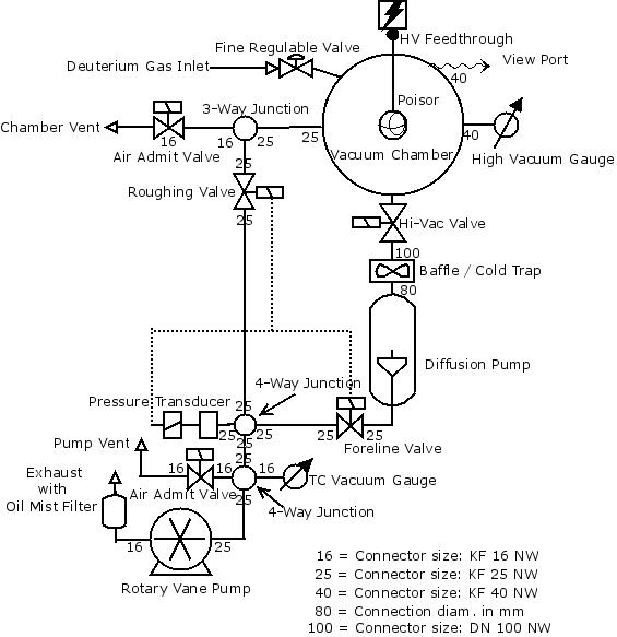 Image 1: Schematic
Layout of the Vacuum System (©FRS 2014)
The numbers in the schematic layout ("16", "25"and "40") are the KF (NW) flange sizes of the connectors. These components are currently present and therefore the dimensions are known. Consequently, where not indicated these components are still to be acquired. From the image it can be concluded that (12/2014) the rotary vane pump with exhaust and oil mist filter are present, as well as the oil diffusion pump, the junctions, short lengths of flexible bellow tubing, the vent valves, the foreline valve and the roughing valve, the TC gauge and the high vacuum gauge. All valves in the vacuum system are either electromagnetically or pneumatically operated.  Foreline Vacuum The first stage of the vacuum line, called the foreline, consists of a roughing rotary vane vacuum pump, a thermocouple vacuum meter with read-out controller, valves and tubing. According to the Fusor Forum FAQ (see reference 2) the foreline pump should preferably be chosen as a two-stage rotary vane pump with a pumping capacity of minimally 2 - 4 cfm (3.4 – 6.8 m3/h) and reach an ultimate partial pressure of minimally 25 microns (2.5x10⁻² Torr). The different units that are in use can drive one crazy! The US-population apparently still uses microns (officially abandoned in the 1970’s) whereas others use Torr or millibar. Nobody uses the official SI unit of Pascal (1 millibar is 100 Pa)! And than I did not even mention that I have a couple of mechanical (Bourdon) gauges that have a divided scale reading in cm Hg! Where applicable I shall convert to the most commonly used units. For those who want to convert the pressures mentioned in this website to equivalent pressures in other exotic pressure units, a pressure converter can be found here (the link opens in a separate browser window). Oil Colour Chart Usually in the foreline vacuum line, rotary vane vacuum pumps will be used running on vacuum oil. Vacuum oil in a rotary vane pump is under constant attack by heat, mechanical forces and degradation by chemical vapours that are pumped off the vacuum chamber. Therefore vacuum oil has a limited life and should be changed with intervals. The color chart below indicates the degree of thermal ageing and therefore the remaining useful life of the oil in a rotary pump (image 2). 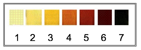 Image 2: Oil Colour
Chart (Source: BOC Edwards)
Oil should be changed before it has reached colour 4. If the oil is allowed to degrade to the extent that colors 6 and 7 are reached, the pump may have suffered damage and should be fully serviced prior to re-use. Servicing ranges from flushing the pomp with rinsing oil to taking the pump apart, cleaning all parts with petrol, replacing seals and vanes if necessary. Since colours on the computer screen or when printed may differ from the original a listing of the colours according to the Pantone system follows:
Vacuum pump No. 1 Some time ago a used Leybold-Heraeus Trivac S2A vacuum pump (Image 3) was acquired with (according to specifications, see reference 3) a nominal pumping speed of 3.2 m3/h, an ultimate partial pressure of < 4 x 10⁻² mbar (3x10⁻² Torr, 30 micron) and an ultimate partial pressure with gas ballast of < 1 mbar (7.5 x 10⁻¹ Torr, 750 micron). Should this used pump still reach its specifications, than it appears to be just barely suitable for the project of building a Fusor. Anyway everything depends whether the foreline pump will be capable to keep up with the diffusion pump. For testing the condition of the used pump a thermocouple (TC) sensor was connected directly to the inlet of the pump. Both the TC and the connected controller (Edwards TC1) are also “very aged” and the consequence is that neither the sensor nor the controller could be reliable. The pump was checked for having sufficient oil in the reservoir (in this pump the oil was black coloured, which is not too good a sign) and for having a rotating drive shaft, i.e. the pump should not be seized. Furthermore the Edwards OM-2 oil mist filter was cleaned and checked for proper operation. The filter element inside the filter housing was extremely dirty and worn. Because the original filter element was no longer available on the market it was replaced by two stainless steel sponges, which were pressed into the filter housing. The filter housing was assembled in such a way that the inlet opening was as far as possible away from the outlet opening. Of course it is not expected that the two sponges would offer the same filtering effect as the original filter but they may slow down the speed of the fumes and give the oil mist a chance to adhere to the sponges and drip off to the sump with the drain plug. The exhaust of the oil mist filter was then connected to a hose leading outside the workshop into the open air. The pump was operated with the gas ballast open for 30 minutes. The TC remained at a pressure of 760 Torr. After 15 more minutes the gas ballast was closed and the pump pressure indicator slowly moved to around 1 Torr. Pumping continued for another hour and the best vacuum that could be obtained was 2x10⁻¹ Torr (200 micron). The pump was quite hot now and that was a good moment to drain the oil from the pump reservoir. It came out totally black. With a new charge of oil pumping started again with gas ballast for 30 minutes, followed by direct pumping at the TC head for another 30 minutes. The pressure was now 10-1 Torr (100 micron). Another hot oil change was performed. The old oil came out now as medium to dark brown. Again two runs with and without gas ballast revealed that the pressure with gas ballast came up to slightly better than 8x10⁻¹ Torr (800 micron), which is conform specifications, whereas the pressure without gas ballast reached 8x10⁻² Torr (80 micron). This is still not up to specifications, but how good is the TC system and how good are the KF vacuum connectors? And can we expect an old pump to reach its specifications as when released as new? Another issue that occurred during the last long run is that the pump stopped due to overheating. Overheating of this type of pumps usually occur amongst others when the screen in the inlet line or the filter in the outlet line is clogged. A new step therefore would now be cleaning of the internal filters and screens in the pump. In order to be sure that the TC sensor has no greasy dirt colllected at the thermocouple it was cleaned by several rinses with Naphthalene (cleaning petrol) followed by a rinse with propanon (acetone). 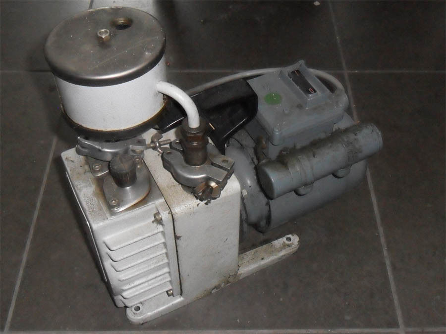 Image 3: Leybold-Heraeus Trivac S2A rotary
vane pump with Edwards oil mist filter (©FRS 2014)
The vacuum pump inlet was opened and the internal oil filter was removed and cleaned in Naphthalene. Then the pump was filled with a mixture of 50% vacuum oil and 50% kerosene and kept running for an hour. After draining, replacing the internal oil filter and filling the pump with grade 19 vacuum oil up to the level it was run with gas ballast for one hour and the vacuum obtained was checked: 1Torr. Running the pump alternatively with and without (inlet closed) was continued for three days (6 hours per day) resulting finally in a vacuum of 1 Torr at gas ballast and 2x10⁻¹ Torr without gas ballast. Another hot oil change was performed and then the pump was again operated alternatively for six hours with and without gas ballast and finally an ultimate partial pressure with gas ballast was obtained equal to the specifications (0.8 Torr or 800 micron), whereas the ultimate partial pressure without gas ballast was 0.1 Torr (100 micron) with the pump still very slowly improving. After some days of running the ultimate partial pressure without gas ballast was never better than 9.5x10⁻² Torr (95 micron) and therefore it was decided to change the grade 19 vacuum oil for a grade 20 vacuum oil which has a higher viscosity (is thicker). After draining the pump from grade 19 oil and a cleaning run with grade 20 oil, followed again by draining the pump, a fresh load of grade 20 oil was filled into the pump. Degassing was performed during an hour and then a long pumping run was done. At the end it showed that with gas ballast a pressure of 7x10⁻¹ Torr (700 micron) was observed and an ultimate partial pressure without gas ballast of 3.6x10⁻² Torr (36 micron), which is almost as good as the factory specifications for this pump (3x10⁻² Torr, 30 micron). From this experience can be concluded that after cleaning it takes very long pumping runs to liberate the vacuum pump from residual cleaning solvents! Cleaning the pump has resolved the problem of overheating during a long run. The vacuum pump can be kept pumping now for long runs of many hours and the outer casing will only warm up to about 45ºC. The complete procedure of cleaning and using a proper grade of vacuum oil restored the pump to its original specifications. The use of this pump is mainly in combination with a turbomolecular pump, for which the pumping speed and the ultimate partial pressure obtained are more than sufficient. Precautions, however, need to be taken to prevent backstreaming of oil. Vacuum Pump No. 2 The second vacuum pump that was acquired (eBay: € 78.77) is a Vacuubrand type RD4, a two-stage sliding vane rotary vacuum pump with a pumping capacity of 4.3 m3/h, an ultimate partial pressure of 2x10⁻⁴ mbar (1.5x10⁻⁴ Torr or 0.15 micron), which is considered sufficient for complying with the minimum requirements for Fusor operation (image 4). 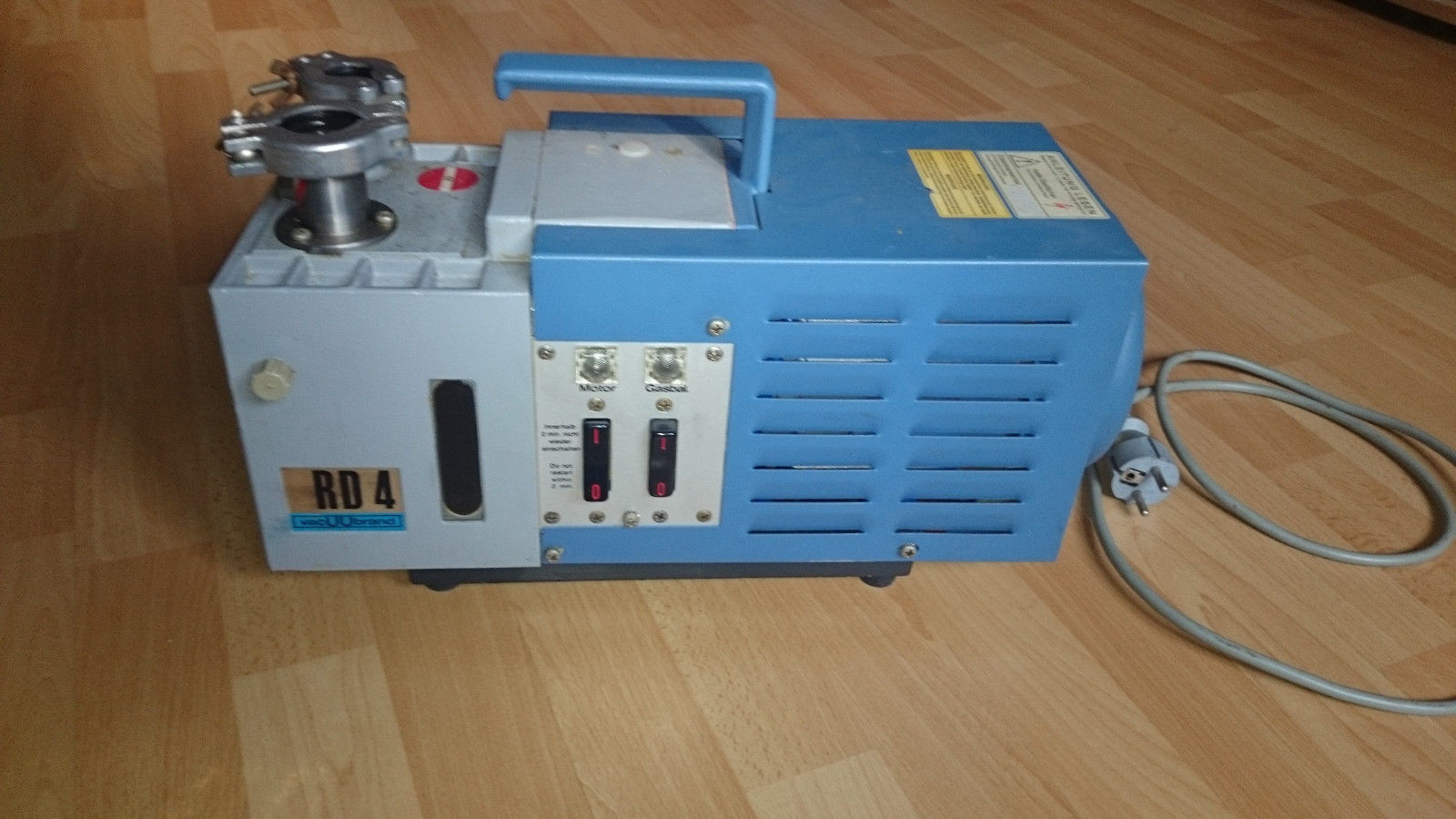 Image 4: Vacuubrand
two-stage sliding vane rotary vacuum pump, type RD4
The vacuum pump has a KF25 inlet connector and a KF16 outlet connector with a type FO 10/8 exhaust filter in a housing attached to the pump (image 5): 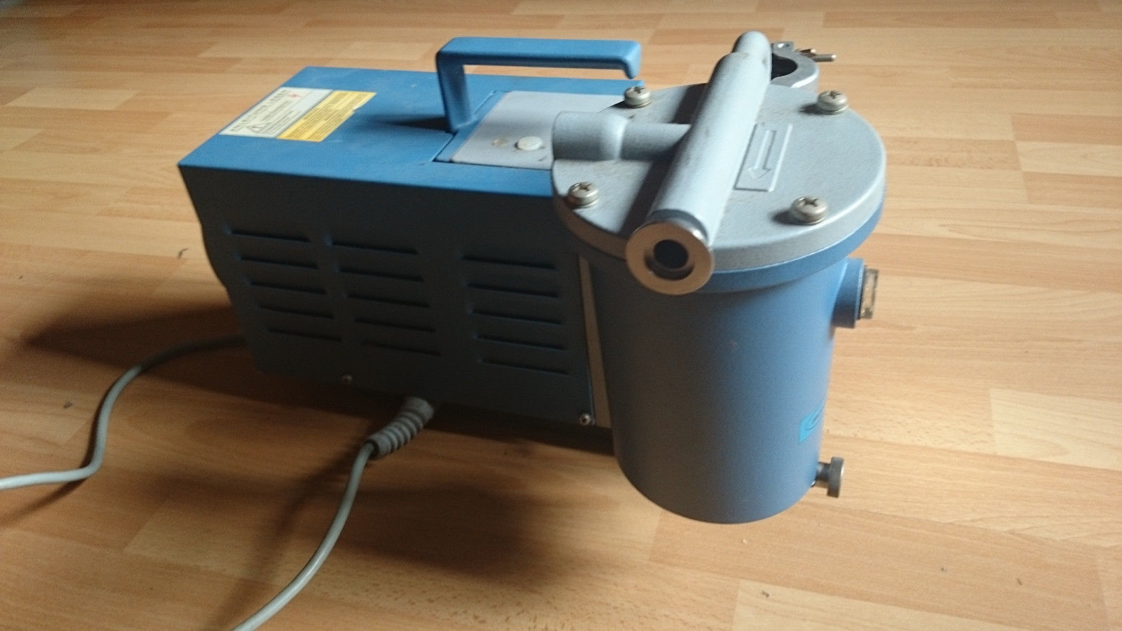 Image 5: Vacuubrand
RD4 with exhaust filter
The manuals for the Vacuubrand RD series of sliding vane rotary vacuum pumps are diificult to find on the internet as these vacuum pumps are rather dated now. The vacuum pump that was acquired (images 4 and 5) dates from 1989, currently 25 years old, but it looks if it just came from the showroom. Nevertheless, despite the age they appear rather frequently on eBay and therefore they must be reliable and robust. A PDF copy in the German language only can be downloaded here: RD manual, but it does not contain an exploded view of the RD4 vacuum pump; The complete manual in both German and English, including an exploding view, can be downloaded here: RD manual complete bilangual and the manual in both German and English for the FO 10/8 and FO 25/30 exhaust filters can be downloaded here: FO exhaust filters. As mentioned, when the RD4 arrived it looked like new but it was not possible to see if any oil was present in the oil reservoir as the glass was dark brown to black coloured by oil residue. The first test was to find out if the motor axis would turn: no problem. Even when the pump would have been drained prior to shipping, some oil is always present and therefore it does not harm to switch it on for a short moment: it started running with a blubbering sound and a quick test with a hand over the inlet port gave a biting feeling of the underpressure that started building up immediately. Quite promising! Next steps are opening the drain and the oil inlet to see if the pump was indeed drained prior to shipping, followed by draining if not drained and then filling with rinsing oil and running the pump until warm and then draining the rinsing oil. The rinsing procedure is repeated until the rinsing oil drains as a clear liquid. Rinsing oil can be bought ready for use or it can be made by mixing 50% vacuum oil with 50% kerosene (paraffin oil) or fuel oil. The vacuum pump should run for 30 minutes with rinsing oil and than be drained thoroughly when the pump is still warm. Then refill again with rinsing oil until clear after drainage and then fill with standard vacuum oil. An unpleasant smell can develop when operating the pump again in daily use, after using the kerosene rinsing mixture and even the more when fuel oil will be used in the rinsing mixture, but the smell will disappear after some time. Please note that some vacuum pump manufacturers warn against the use of kerosene for rinsing their pumps. Check if this is the case with your pump and change to a suitable, recommended rinsing fluid. In general, great care should be exercised when a kerosene mixture is used, as kerosene is volatile and ignites at a relatively low temperature, far lower than vacuum oil. Therefore do not use pure kerosene only as a rinsing fluid, but always mix with vacuum oil and do not run the pump too long on the rinsing mixture to avoid overheating. Always mix the two fluids outside the vacuum pump in a suitable container and observe if the mixture is stable, i.e. the two liquids do not separate or flocculate after mixing. The next step is to take a sample of the rinsing fluid and add a small volume of the original, dirty oil that came from the vacuum pump when drained for the first time. Mix throughly and observe if the old oil dissolves fully in the rinsing fluid. When this is the case one can be sure that the rinsing fluid is suitable for cleaning the pump. Of course, there is still no guarantee that the rinsing fluid is compatible with the seals and valves inside the pump, that remains a risk to be taken. However, when the vacuum pump was originally filled with a mineral vacuum oil, the kerosene/vacuum oil mixture will do no harm to the vacuum pump. When the pump is finally filled with 750 ml vacuum oil, grade 19, 20 or 70, tests can be run to find out if the specifications can be met: an ultimate partial pressure of 2x10⁻⁴ mbar (1.5x10⁻⁴ Torr or 0.15 micron), an ultimate total pressure of 2x10⁻³ mbar (1.5x10⁻³ Torr or 1.5 micron) and an ultimate partial pressure with gas ballast of 4x10⁻³ mbar (3x10⁻³ Torr or 3 micron). The choice of vacuum oil for the RD4, a two stage rotary vane pump, is either a grade 15, a grade 19, a grade 20 or a grade 70 vacuum oil. From one brand of oil (BOC Edwards Ultragrade), we have compared the specifications in table 1:
Tabel 1: Comparison
of vacuum oils
These four different types of oil have more or less the same price and therefore price is not a decisive factor. The standard vacuum oil for medium sized rotary vane vacuum pumps is grade 19 and it is advised to use this vacuum oil when frequent oil changes are foreseen (due to vacuum applications, e.g. in a laboratory, which pollute the oil rapidly). Ultragrade 70 is advised for large, industrial pumps running more or less permanently in industrial applications. The viscosity at 40°C for grade 70 oil is in between the viscosities of grade 19 and 20 and it is assumed that the higher the viscosty at an elevated temperature the better performance can be expected from an older pump with possibly worn vanes. A higher viscosity at 20°C probably means that the motor of the pump has more labour to perform to get and keep the pump rotating. Too thick an oil might overheat the pump. The original oil that was changed from the RD4 was rather viscous, but highly contaminated. Rotary vane pumps generally have low clearances and therefore require a low viscosity oil, i.e. in this case Supergrade 19 is recommended. Cleaning of Pump No. 2 FO 10/8 Exhaust Filter It does not seem logical to start with cleaning the exhaust filter when both the vacuum pump and the filter need to be cleaned, but lacking fresh oil for the vacuum pump it was decided to start with the filter first. The Vacuubrand FO 10/8 exhaust filter has a maximum permissible airstream of 8 m3/h. The pressure build-up/filter resistance at maximum volum of airstream is 0.3 bar. The filter has a spring loaded safety valve, which opens at 1.5 bar and blows off into the open air. The filter housing was opened by removing the four screws on the top of the filter head and pulling off the head. Noticing the rather large dimensions of the total filter unit it is quite a surprise to see that the actual filter is quite small. The reason is that the basin has an oil catching capacity of 700 ml. The filter element, with a Vacuubrand catalogue number 667077, has been made of a synthetic resin with embedded glass fibers; it has a cylindrical shape with a height of 30 mm, an outer diameter of 70 mm and a wall thickness of 15 mm. That leaves an inner open space with a diameter of 40 mm. Such a filter element retains 99.99% of mineral oil mist by precipitation. 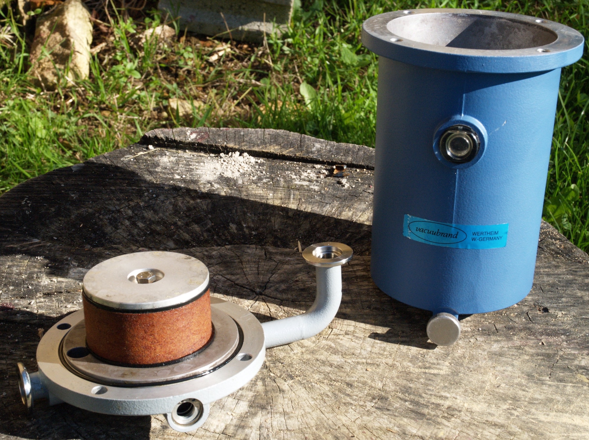 Image 6: Exhaust
Filter (© FRS 2014)
Image 6 shows the opened exhaust filter. At the right the blue housing with an oil level window and a drain screw. At the left the head (after cleaning) with two KF16/10 connectors; the straight connector far left is the filter outlet and the right angled connector in the center of the image is the filter inlet connector. The opening at the front of the head is the spring loaded safety valve. The filter element is the brown coloured cylinder between two black gaskets and fixed to the head with a metal plate (top) with a fastener screw in the center. The head closes air tight onto the housing with an O-ring. The exhaust filter was very dirty inside the housing and inside the filter element. Cleaning the housing was quite easy with Naphthalene (dry cleaning naphtha, a.k.a. cleaning petrol or lighter fuel) but the filter element was harder to clean. First of all, vacuum oil had deteriorated into a resin like substance and glued the filter element onto the filter head. The filter element was removed by filling the head with Naphthalene through the filter inlet port with the center filter fastening hole in the bottom plate open (i.e. fastening screw removed, which makes air escape), closing the port after filling with a KF16/10 blind plate and clamp, putting a blow gun on the hole of the fastener screw of the element (center hole in the bottom metal plate on the filter element) and giving a short blow with compressed air. This will blow off the element from the filter head but be sure to wrap the head in a cloth in order to catch parts that get blown off. Please also note, that all work with Naphthalene needs to be done in the open air, away from electric appliances and open fire, because a mixture of Naphthalene and air is explosive and Naphthalene as such is highly flammable. Wear nitrile gloves during all operations with vacuum oil and/or Naphthalene because the cleaning liquid is an irritating substance and may induce cancer. Moreover, it is unknown what kind of poisonous or carcinogenic substances may have been pumped as vapour through the vacuum pump and are concentrated in the oil and dirt inside the pump and exhaust filter. When the filter element is separated from the filter head and when the seals on top and bottom have been removed, soak the filter element for a couple of hours in a closed container with Naphthalene (closed, because Naphthalene evaporates rapidly in air). After soaking, brush the wet element inside, outside, top and bottom gently with a fine (copper) wire brush, in between followed by repeatedly brushing with a paint brush soaked with Naphthalene until all dirt has been removed. Immerse and soak again for a while, brush again and finish with blowing compressed air through the filter element, from the outside to the inside (i.e. in the direction opposite the normal exhaust air flow direction when the vacuum pump is working), by holding the tip of the blow gun on the outer surface of the element and moving the tip over the total outer surface of the filter while blowing. During blowing with compressed air, rinse the filter element regularly with fresh Naphthalene. Install the cleaned filter element on the filter head, fasten it with the fastener screw and blow it fully dry with a blow gun with compressed air through the inlet port (the port that connects to the pump). Blowing dry is important because of the flammable. explosive fumes that may come off the filter, if not fully dry, when attached to the vacuum pump and made to operate. Moreover, while blowing dry it can be checked that the filter is freely passing air through it without engaging the safety valve, or with other words, one can be sure that the cleaning has been succesful. When all the dirty work has been finished we can fully satisfied conclude that € 70,00 for a new filter element is still unspent in our pockets! RD4 Pump After having cleaned the oil mist exhaust filter the vacuum pump was the following item to tackle. When a number of rinsings with a vacuum oil/paraffin mixture had been done, the rinsing oil still was black when drained. A more drastic approach was therefore performed by rinsing the vacuum pump by short runs after filling with pure Naphthalene. Even when this should not be succesful than at least it would clean out a lot of dirt in advance in case the housing needed to be opened for taking the pump apart for a thorough cleaning of all individual parts. Vacuum Pump No. 3 & 4 At a later stage of the project we also received a BOC Edwards E2M1.5 two stage rotary vane vacuum pump, serial number 07229, (image 7), followed two weeks later by another incomplete one for spares, serial number 09495 (image 8). 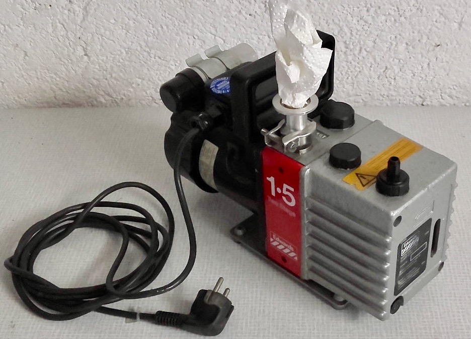 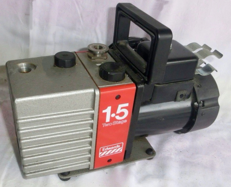 Image 7 (left) and 8 (right): Two Edwards E2M1.5 Rotary Vane Vacuum Pumps (Source: suppliers) These pumps have the following specifications: The pumping speed is 1.8 m3/h at 2800 rpm (230V, 50 Hz); the ultimate vacuum (partial pressure) without gas ballast is 5 x 10⁻⁴ mbar (3.7 x 10⁻⁴ Torr), the ultimate vacuum (total pressure) is 1.5 x 10⁻³ mbar (1.1 x 10⁻³ Torr) and the the ultimate vacuum with gas ballast (partial pressure) is 2.5 x 10⁻² mbar (1.9 x 10⁻² Torr) (See diagram image 9). The maximum oil capacity in the sump is 0.32 liter and the pump runs on Edwards Ultragrade 15 vacuum oil (see table 1). 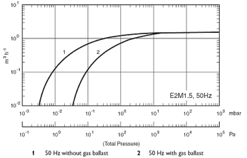 Image 9: Performance Diagram Edwards E2M1.5 Vacuum Pump (Source: Manufacturer) The first Edwards E2M1.5 pump has the standard hose barb as the outlet connector and the second pump has the outlet connector missing. The thread in the pump housing is 3/8" BSP female. For easy connecting of an oil mist filter we decided to fit a type 314 stainless steel KF16 flange with 3/8" BSP thread (image 10). 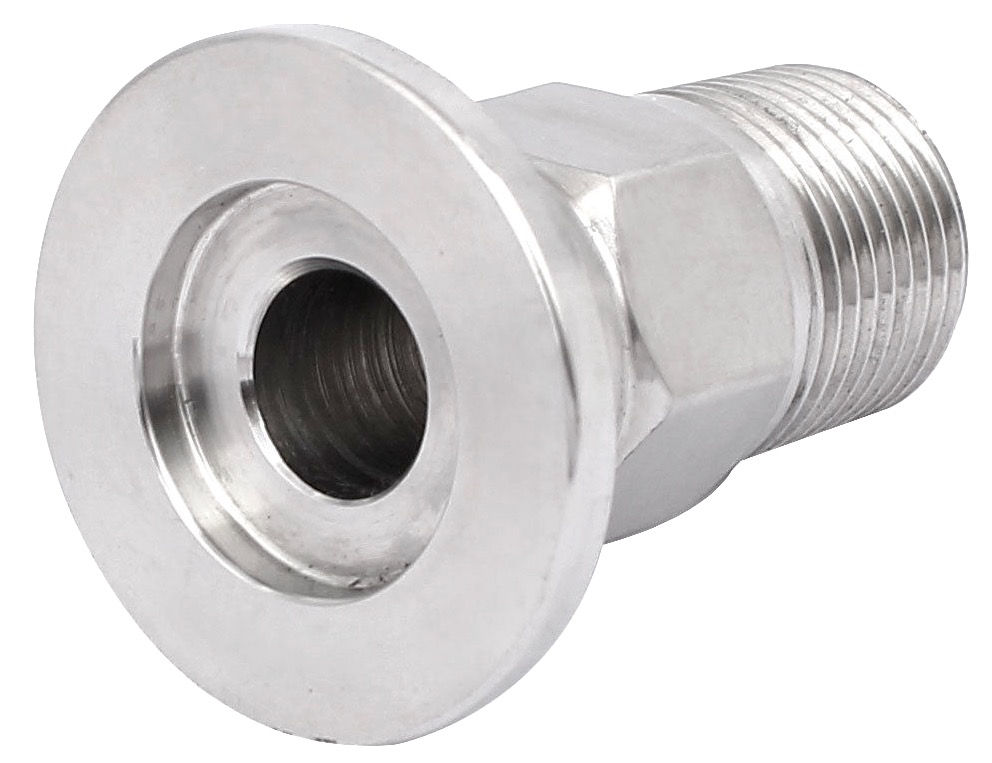 Image 10: KF16 flange with 3/8" BSP thread (Source: supplier) Cleaning of Pump No. 3 Similar to all previous pumps, the first Edwards E2M1.5 vacuum pump looked like new apart from a transport damage to the plastic cover of the motor. Moreover, the cooling fan on the motor end shaft had been pressed against the motor housing, due to the transport damage, and therefore the motor did not run when connected to 230V AC. This was quickly cured by pulling the fan slightly away from the motor housing by using a mechanical bearing puller. The second Edwards E2M1.5 vacuum pump had a missing start capacitor (8 µF, 450V) and the motor was said to have a short cut. The idea is to canabalize the second pump for optimizing the first pump, but we shall try to find out first if the short cut claim is correct. For that purpose a schematic of the electric connections for the motor is shown in image 11: 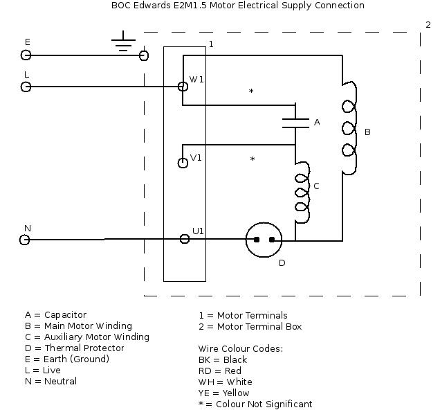 Image 11: electric wiring diagram for the E2M1.5 motor (Source: Edwards manual) According to the Edwards E2M1.5 manual the earth connection should measure a resistance of less than 0.1 Ω, whereas the insulation resistance should be better than 10 MΩ. After filling the first (complete) pump with a shot of used (but good) oil of the correct type we set the pump running with gas ballast for 30 minutes, closed the gas ballast and had it drawing vacuum for 10 more minutes and then measured the vacuum obtained. The vacuum obtained was not more than a lousy 1 Torr and the oil had turned brown. Again we had obtained another heavily contaminated, defective vacuum pump! Of all pumps that we acquired, we never received a reasonably good one in a decent shape. In our opinion all vacuum pumps sold for affordable prices are either defect (motor or broken vanes) or they are heavily contaminated up to a state where recovery to normal appears to be impossible, unless a revision set of parts (containing seals and vanes) is bought. We started running the pump during consecutive charges with cleaning fluid until hot, followed by fluid changes until a clear liquid was obtained. High Vacuum Line The high vacuum line consists of an oil diffusion pump and a valve. It connects to the vacuum chamber (reactor) and it is separated from the vacuum chamber with the valve. The Fusor high vacuum will be obtained with an oil diffusion pump despite the fact that a turbomolecular pump is also present in our collection of vacuum parts. Why the preference for an oil diffusion pump? The reason is simple: for the turbo pump a power supply/controller and the connecting cable are still missing and they are difficult to find (for a reasonable price). More about the oil diffusion pump can be found in the next paragraphs and more about the turbo molecular pump can be found on this page in the section Turbomolecular Pump. An oil diffusion pump contains oil, or better a fluid, which is heated up to boiling temperature. The vapour of the boiling fluid is sprayed by jets onto (cooled) walls and "catch" molecules of gas in the vacuum system. After hitting the cooled wall the fluid vapour condenses and returns into the boiling pot, where the process is repeated. Different types of fluids are available, which each have specific characteristics for reaching a required high vacuum. My oil diffusion pump came with a bottle of "Alcatel 215" pump fluid, of which no specifications could be found. Searches on the internet revealed that "Alcatel/Adixen 214" diffusion pump fluid does exist and it is supposed to be equivalent with Dow Corning 704© diffusion pump fluid, a well known and widely used fluid for diffusion pumps. The specifications should be: Vapour pressure at 25°C: 2 x 10⁻⁷ Torr Viscosity at 40°C: 24 cst. Specific gravity at 22°C: 1.07 g/ml Boiling point - C.O.C: 215°C Flash point - C.O.C.: 221°C The Alcatel fluid concerns a single component silicone fluid engineered for high vacuums in the range of 10-6 Torr untrapped to 10-8 Torr trapped. The choice for an oil diffusion pump as a primary choice is mainly because of budgetary reasons. Probably a better choice could be made for a turbo molecular pump because these high vacuum pumps work without backstreaming of oil vapour, which is a disadvantage of oil diffusion pumps. When categorizing oil diffusion pumps, they belong to the category "quiet and dirty, whereas a turbomolecular pump is in the categories "noisy and clean" when they have magnetic bearings and "noisy and dirty" when they have oiled bearings. The price for a used turbo molecular pump including its controller is unfortunately rather high; for new equipment the price difference between a complete oil diffusion pump and a complete turbomolecular pump (i.e. including controller and power supply) is a factor ten! The same factor ten extrapolates to used equipment. Low capacity turbo pumps are scarce and the realistic risk exists that the pump is worn (usually the bearings and/or the turbine blades) and repair is also costly. Turbo molecular pumps rotate at speeds of 20.000 up to 90.000 rpm and are therefore subjected to wear. Oil diffusion pumps are not difficult to find and usually have a favourable capacity. Moreover oil diffusion pumps have no moving parts and except the heater nothing can brake down. Oil Diffusion Pump The oil diffusion pump in the high vacuum line is an Alcatel, model 6063, built in 1987. See Images 12 and 15. The pump has about the size of a 0.75 liter wine bottle and it is a water cooled version. An air cooled version would have been easier to operate because it is rather costly to operate a water cooled oil diffusion pump on running tap water. A cooling system will therefore have to be developed and built consisting of a water reservoir (buffer), a water pump (water recirculation) and a heat exchanger (e.g. old car radiator with an electric fan). Image 12 (center of the image) also shows a thermal circuit breaker (Klixon) placed on the cooling tubes. The thermal circuit breaker is of the normally closed type (NC) and it is marked 210/05/87, Microtherm R20. The function of the circuit breaker is to disconnect the heater(s) when the pump becomes too hot (failure of cooling water supply). 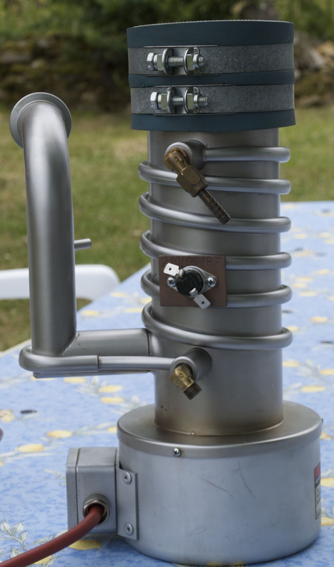 Image 12: Alcatel Oil
Diffusion Pump (© FRS 2014)
The outlet, to which the foreline pump will be connected, has an opening suitable for a KF 25 coupling. In the outlet tube leading to the oil diffusion pump is a narrow shunt, probably for connecting a vacuum sensor, or a vacuum switch. See Image 13. The oil diffusion pump can only start its operation when a vacuum of < 0.5 Torr (even better 2.5x10⁻² Torr) has been reached and this can be controlled by the sensor or switch connected to the shunt. 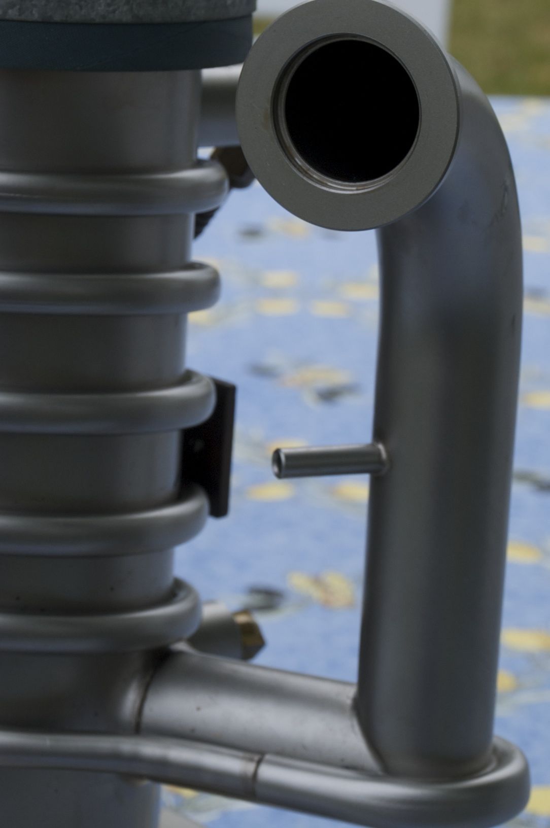 Image 13: Outlet of
the Oil Diffusion Pump with Shunt (© FRS 2014)
The cord that is connected to the connection box has four coloured wires: black, brown, blue and yellow/green. The colour coding is shown in Image 14, which translates as follows (table 2):
Table 2: Translation of Wire Codes from German to English Apparently, this oil diffusion pump has a heater and a pre-heater. An extensive search on the internet did not yield any information about oil diffusion pumps which have a pre-heater and a heater. It could be that a cold pump is started with both heaters and that, when the operating temperature has been reached, the pre-heater is switched off. Alternatively, it could be that the pump is pre-heated when the foreline pump is still evacuating the vacuum system and that the pre-heater is switched off when the operating vacuum has been obtained, simultaneously switching on the main heater element. The latter of these options appears probably to be right. Searching for more knowledge about the operation and use of oil diffusion pumps I succeeded in finding the (said) standard book on diffusion pumps (reference 4). This publication learned that high vacuum pumps need a period of conditioning, due to gas evolution from walls and fluids being present. A warm-up time of 20 to 30 minutes is required before full pumping action of the jets inside the pump is established. During that time the vacuum system can be evacuated by mechanical pumps. The pressure created by the mechanical pump must be below 0.5 Torr before the pumping fluid reaches boiling temperature which is typically near 200°C. It seems therefore logical that during evacuation of the vacuum system, the diffusion pump is conditioned by pre-heating. During originally designing the pump, in order to avoid reaching the boiling temperature of the pumping fluid, the heating capacity of the pre-heater must have been chosen at such a level that reaching the boiling temperature of the fluid is prevented. From the resistance measurements below it can be noticed that the pre-heater has a power rating of 140 W, compared to the main heater at approx. 400W and that seems to make sense considering the conditions as discussed. 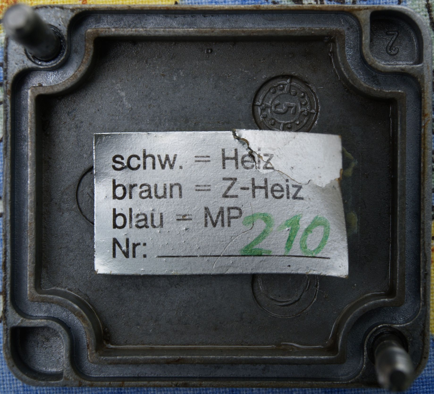 Image 14: Colour Codes
for Connecting (© FRS 2014)
In order to find out whether the oil diffusion pump is in an operational condition and to know more about the capacity of the heaters, all wires were measured against each others and against the housing for resistance. Results can be found in table 3:
Table 3: Resistance
of wires against wires and housing, expressed in Ω
From table 3 can be concluded that no short cuts between wires exist, including between wires and housing (except for the ground wire) and that the housing of the pump is connected with the ground wire. Furthermore a resistance was found between the pre-heater wire (brown) and neutral wire (blue) of 377 Ω and between the heater wire (black) and neutral wire (blue) of 133 Ω. With an operating voltage of 230 Volts this means that the pre-heater draws a current of 0.61 Amps and therefore has a power rating of 140 Watt. Similarly the main heater draws a current of 1.73 Amps and therefore has a power rating of 398 Watt. 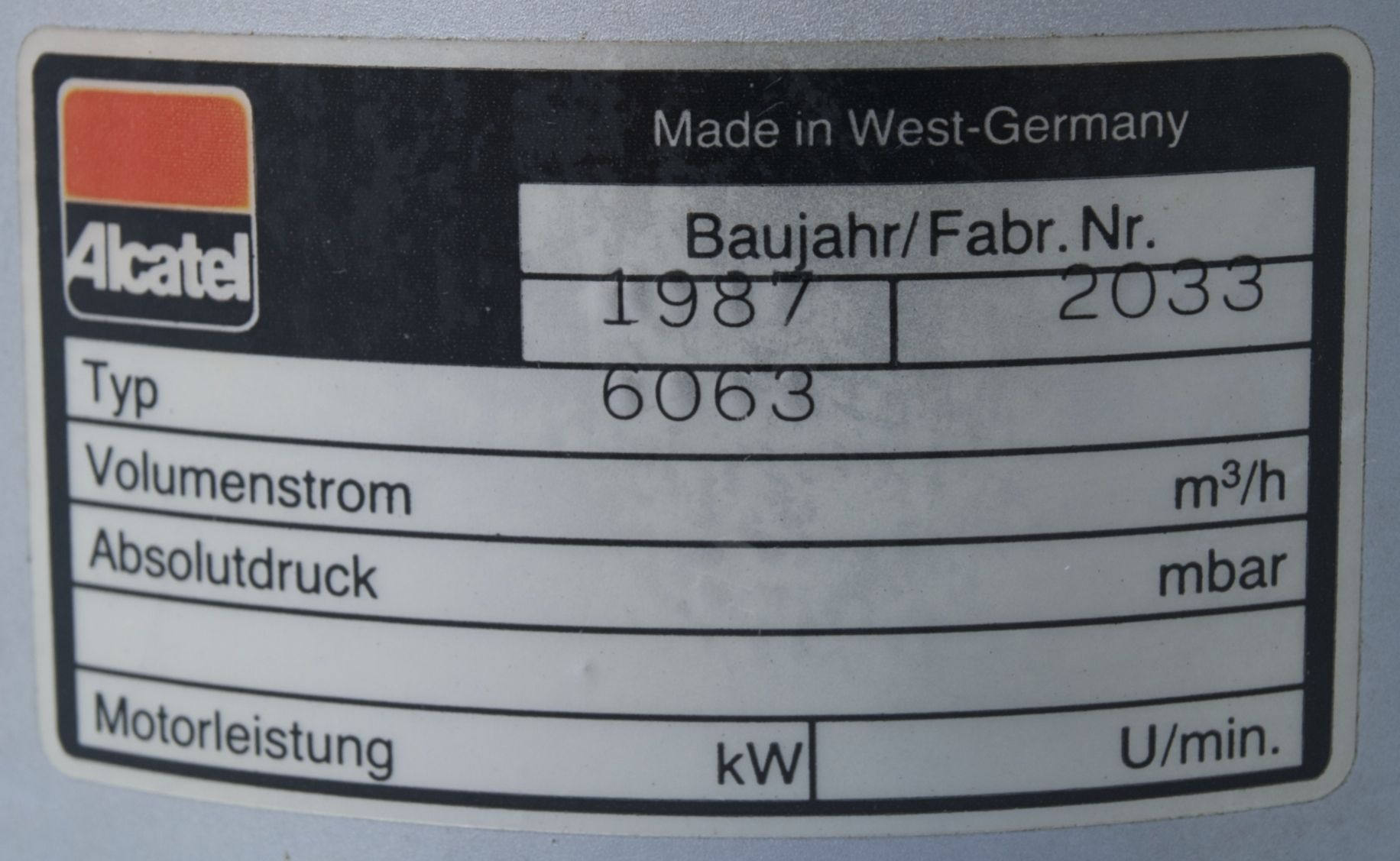 Image 15: Data of the
OIl Diffusion Pump (© FRS 2014)
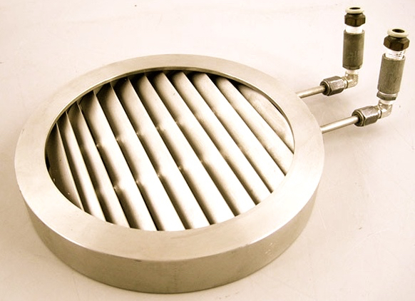
On top of the oil diffusion pump a collar has been attached to connect the pump to the vacuum chamber. See Image 16. The collar contains a grid with probably no other function than preventing that something drops into the pump when maintenance work is performed higher up the line. When the grid had been mounted lower (just above the heater) its function would have been to catch fluid drops that are thrown up by heavy boiling of the fluid and separate them from the vapour because vapour is the only ingredient required for the pumping effect. At the current place of the grid a baffle or cold trap would have been more efficient for reducing backstreaming of the fluid into the high vacuum. Some effect in reducing backstreaming might be expected from the grid but it is certainly less effective than the usual baffle or cold trap. The inner diameter of the collar is 81 mm and a stainless steel tube with 80 mm outer diameter will be required to attach the pump to the vacuum line. The stainless steel tube will need a collar for connecting it to the next stage, a baffle/cold trap or the high vacuum valve separating the oil diffusion pump from the vacuum chamber. For the collar we will braze or weld a DN 100 flange (image 16 and image 17) to the 80 mm diam. tube. The pumping capacity of the oil diffusion pump can approximatively be calculated from the diameter of the inlet (80 mm). According to reference 5 the maximum pumping capacity of an oil diffusion pump for H2 is approx. 4 L s-1 cm-2 at the inlet. For an inlet diameter of 80 mm this equals a pumping capacity of 200 l/s or 724 m3/h. 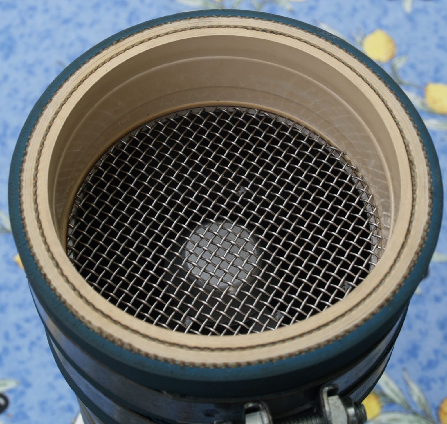 Image 16: Collar of
the Oil Diffusion Pump with Gitter (© FRS 2014)
The DN 100 flange is based on a different system for attaching vacuum components. With increasing diameters of vacuum components the KF/NW connectors fail to ensure a good vacuum and a better clamping system is required, which is found in ISO-DN or Conflat flanges: 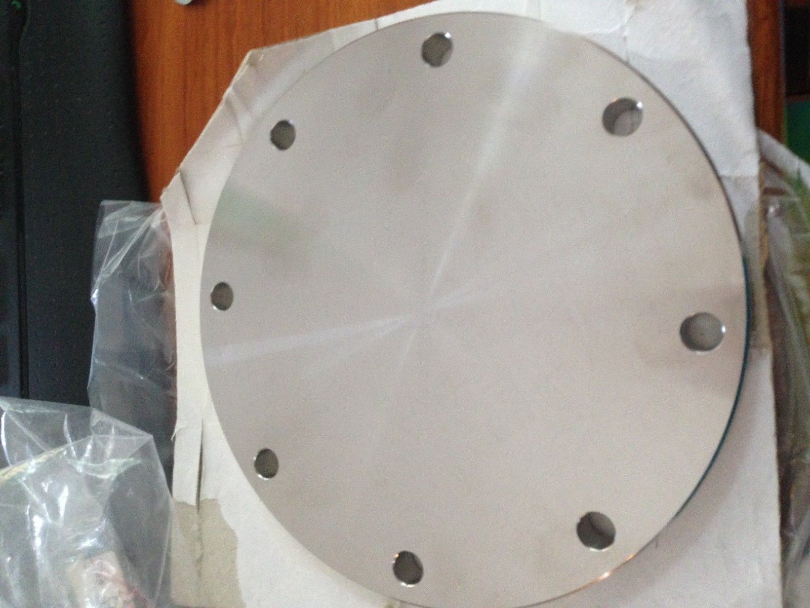 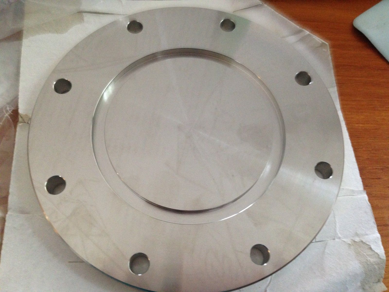 Image 17 and 18: DN
100 flange; left ambient pressure side, right vacuum side (source:
Supplier)
The flange in images 17 and 18 is a blank flange, used for closing off vacuum systems. It is a so-called ISO-F 100 flange. For our purposes a concentric hole with a diameter of 80 mm will need to be turned into the inox flange and the inox tube will be brazed/welded into that hole. Care needs to be taken that the required centering ring with viton seal (image 19) still will fit into the flange as this is essential for obtaining vacuum. 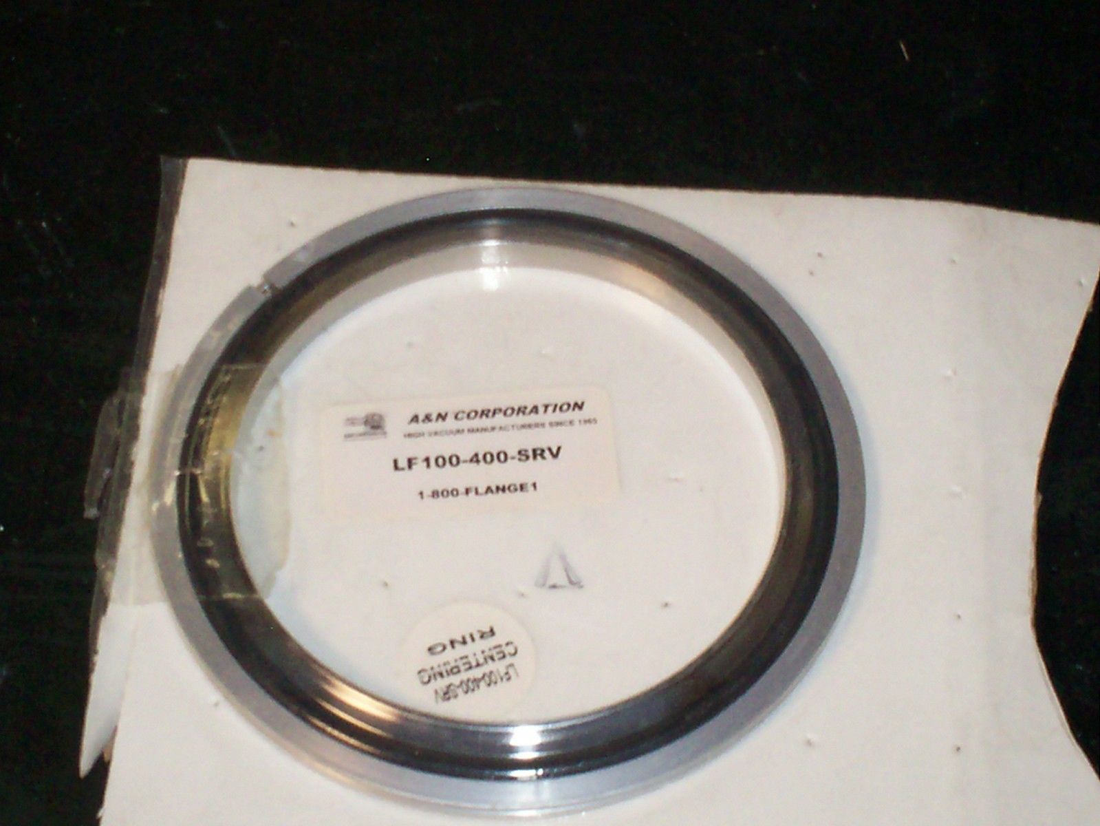 Image 19: DN 100
centering ring with viton seal (source: Supplier)
The actual construction of the connecting part to the oil diffusion pump, including baffle and cold trap will be dealt with on a separate web page: Engineering Works. Baffle and Cold Trap Not all oil from the diffusion pump will be condensed against the pump walls, but a small amount will escape stream up to the vacuum chamber. Oil vapour appearing in the vacuum chamber will be dementrous to the system. Removing backstream oil from the system is performed by a (liquid cooled) baffle and a cold trap. Baffle The baffle in its simplest form consists of one of more barriers, which obstructs the direct flow and forces the backstream gas flow to change its direction abruptly and to reduce its speed. The heavier vapour particles end up against the barrier, condensate and drop down as fluid. Baffles can be obtained as ready to use units from vacuum material suppliers, but they can also be constructed by a skilled metal worker. Two stainless steel air gitters are required with a sufficiently large diameter. Because a large reduction in air flow capacity is unwanted, the baffle diameter ususally is oversized in dimensions when compared to the inlet diameter of the diffusion pump. In our case we have a diffusion pump inlet surface of about 4778 mm2 (internal diameter 78 mm) and when the slits in the air gitter should have an open space of 50% of the total surface, than the diameter of the air gitter should be minimally 110 mm in order to obtain an unchanged gas passage (image 20: measure the height of the slits (h) and their length (l), multiply h*l and summarize the results to find the total open surface). Gitters, however usually have a far lower open space than 50% and for an unchanged gas flow we may end up with an unrealistic large gitter diameter. For a gitter with an outer diameter of 125 mm the height of the slits are 3 mm and the total length of the gitters is 520 mm. The surface of open gitter space is therefore 1560 mm2, which unfortunately yields a restriction of 33% to the air passage. The baffle can act as a choke in the high vacuum system 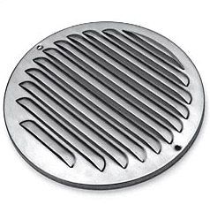 Image 20: Stainless
steel air gitter (Source: Supplier)
The two air gitters are arranged opposite to each other (image 21) in a cylindrical housing with fittings that match to the oil diffusion pump (bottom) and the cold trap or high vacuum valve (top). 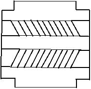 Image 21: Arrangement
of (dimensionally oversized) air gitters to form a baffle (© FRS 2014)
Image 21 is unfortunately unclear in so far that it does not show the exact positioning of the airways. They should be placed in a way that looking through the baffle (top downwards or bottom upwards) does not permit a straight open view through the baffle, i.e. absence of a direct line-of-sight. Cold Trap Additionally, a cold trap can be placed on top of the baffle or it can be combined within the baffle. The function of the cold trap is to freeze out water vapour in the gas flow and to trap backstreaming oil vapour that still might have passed the baffle. A cold trap is usually cooled with liquid nitrogen but this is neither necessary nor is it a safe choice. Apart from the problem to obtain a supply of liquid nitrogen the low temperature of the cold trap in combination with the high vacuum might freeze out oxygen, which collects in the cold trap and forms a danger due to its explosive character in combination with oil vapour when operation of the system is stopped and as a result the vacuum system starts warming up. When constructing a baffle a cold trap can be eliminated by integrating a cooling sytem in the baffle (to obtain a cooled baffle). This can be done by placing a coiled tubing (image 22) between the two air gitters with the gitters attached to the cooling tube. An inlet and an outlet port through the baffle wall are fed with a cooled mixture of water and anti-freeze (e.g. ethylene glycol or propylene glycol) or with pure anti-freeze when temperatures below -10°C are required. It is noted here that pure ethylene glycol has a melting point of -13°C and propylene glycol of -59°C, i.e. the liquid becomes solid below these temperatures. The cooling fluid is cooled with laboratory cooler or with a computer processor cooler operated by a Peltier element. Temperatures of about -25ºC can be reached with such a Peltier driven system, which is sufficient for our purposes. It should be noted that the cooling process of the cold trap should be started only when the vacuum system has a sufficiently low pressure (i.e. a sufficiently high vacuum) to prevent blockage of the cold trap by trapping of too much water vapour at low system pressures. 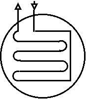 Image 22: Cold trap
layout (© FRS 2014)
The proposed system of a baffle and an externally fed cooler is not uncommon. Image 23 shows such a commercial unit, though somewhat simpler than the one proposed above. The commercial unit has just a single baffle, which has been attached to a single turn coiled cooling tubes, with one end incoming and the other one outgoing.
The cooling element from image 22 has approximate dimensions of 210 mm outer diameter and a height of just over 30 mm. Lacking recognisable flanges, it remains unclear how this element is to be mounted into a vacuum system with the tubular in- and outlet crossing the wall of the vacuum system whilst keeping vacuum intact. The required Peltier cooler unit can be constructed from individual parts intended for liquid cooling of computer processors or it can be obtained complete as a working unit for the same processor cooling purpose. Image 24 shows an example of a commercially available Peltier cooler unit: 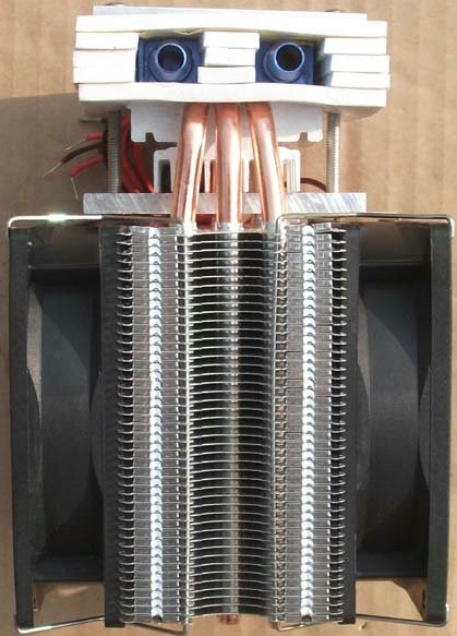 Image 24: Peltier
cooler unit (© supplier 2012moon816, China)
The Peltier cooler unit (image 24) consists of a heat exchange block (bottom centre) with two 12V DC ventilators to dispose of the produced heat at the hot side of the Peltier element. The heating block is connected with three heat pipes to a heat conducting contact block that is pressed to one hot side of the Peltier element. The other cold side of the Peltier element is pressed against an (insulated) radiator with two tubing connections (top of the image). The Peltier element, a TEC1-12715, requires a 12 V DC power supply at 6 Amps. The power supply should be sufficienly rated to power the Perltier element, the two fans and a small circulating pump. The TEC1-12715 element has a deltaTmax of 70°C at 30°C and therefore theoretically a minimum temperature of -40°C can be reached at an ambient temperature of 30°C. In daily practice we should be happy when we obtain -25°C, due to system losses. Image 25 shows an example of a small impeller circulation pump, running at 12 V DC, 0.33A: 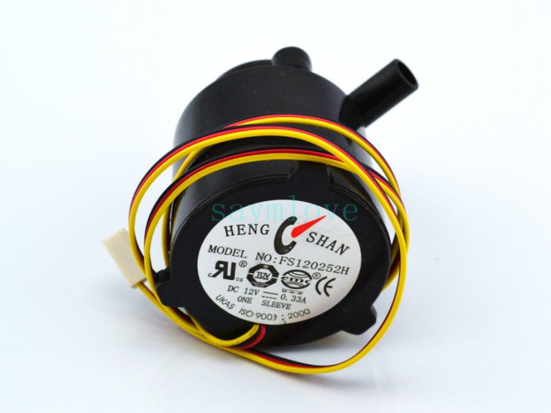 Image 25: Impeller
circulation pump (© supplier Saymlove, China)
Apart from a small buffer reservoir for the cooling fluid, which should have a low volume capacity because the total amount of cooling fluid should be kept as low as possible, a controller for the Peltier element is required (image 26):  Image 26: Temperature
controller with sensor (© Weldt2014, GB)
The temperature controller in image 26 has a controlling range from -40ºC to ~ 120ºC with a precision of ± 0.1ºC. 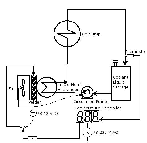 Image 27: Schematic
Layout of the Cold Trap Cooling System (© FRS 2014)
Image 27 shows the rather simple schematic layout of the cold trap cooling system. It is advised to apply heavy insulation to the storage vessel and the tubing to and from the cold trap in order to reduce heat losses, or more correctly: "cold" losses, i.e. warming up of coolant, container and tubing by heat absorption from ambient temperature. Furthermore, it should be noted that the Peltier cooling system is a very inefficient heat pump; the cooling capacity has a low ratio compared to the power consumed from the power supply unit. However, an advantage of a Peltier cooling system is that with simply reversing the polarity of the current, the cooling liquid no longer is lowered in temperature (cooling) but instead the liquid will be raised in temperature (heating). When finishing operation of the baffle/cooler in the cooling mode at the end of the Fusor operation when the vacuum is switched off, this will enable to heat up the baffle/cooler for removal of adhering backstreamed oil, which drops back into the oil reservoir of the diffusion pump. A regenerative cleaning mode therefore has become available now. Cooling System for Oil Diffusion Pump The oil diffusion pump requires a totally different cooling system compared with the cold trap. The difference is that the cold trap is a cold element in a static process in a vacuum system, which has only minor heat losses, whereas the oil diffusion pump dynamically generates continuously large amounts of heat that need to be cooled away. Therefore, the cooling system for the oil diffusion pump requires a large buffer of cooling fluid and a large capacity heat exchanger (liquid to air) such as a car radiator. In a local breaker's yard a car radiator was found with the electric fan still attached. It was removed from a Renault Clio and showed no signs of leakage, though it was a bit rusty (image 28). 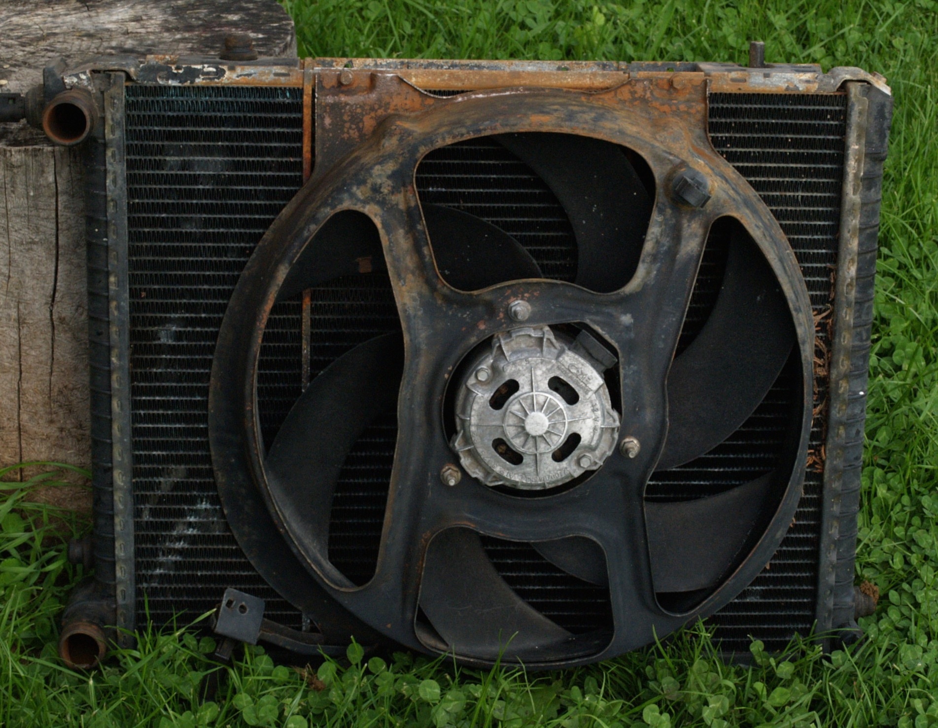 Image 28: Car
radiator with electric fan for use as heat exchanger (© FRS 2014)
The radiator with fan shall be used as a heat exchanger in the cooling system for the oil diffusion pump. Components to be added are a water pump, a buffer reservoir and an electronic circuit for temperature control by means of a speed regulation of the fan. 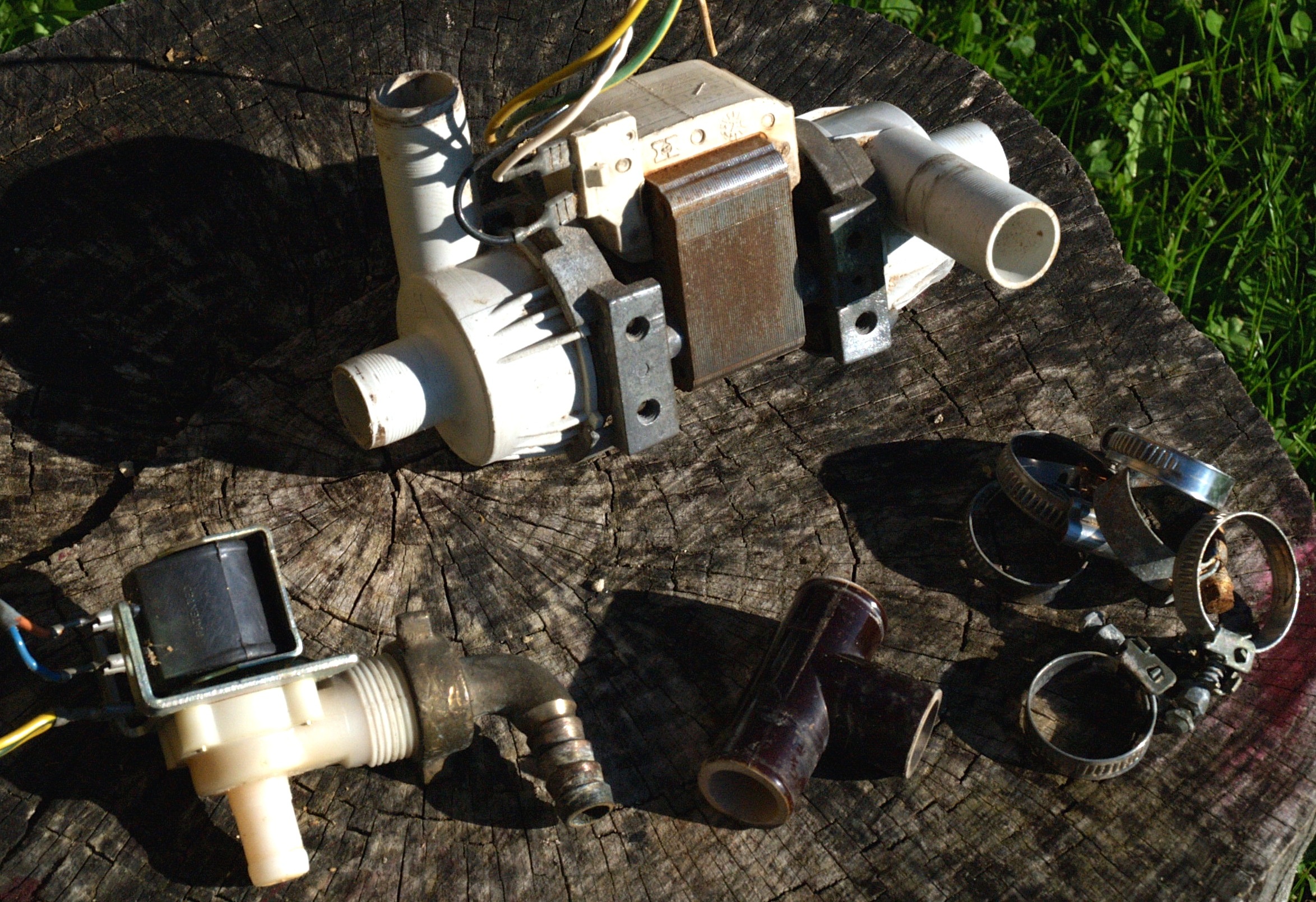 Image 29: Salvaged
parts from old washing machine (©FRS 2014)
Left bottom: electric valve; Center top: double pump unit; Center bottom: T-connector; Right bottom: clamps A waterpump, an electric valve, a T-connector and some clamps (image 29) were dismantled from an old washing machine, an AEG Turnamat S, probably 40 years old. This (indestructible) washing machine consists of a unit containing the actual washing machine and a centrifuge combined in one housing. This meant that the salvaged waterpump has two pumps powered by one electric motor, i.e. one pump for the washing machine and the other one for the centrifuge. As it was not a good idea to have one pump idling (they need water when operated because dry running kills them) the design of the cooling system had to be drawn for double pump operation (image 30): 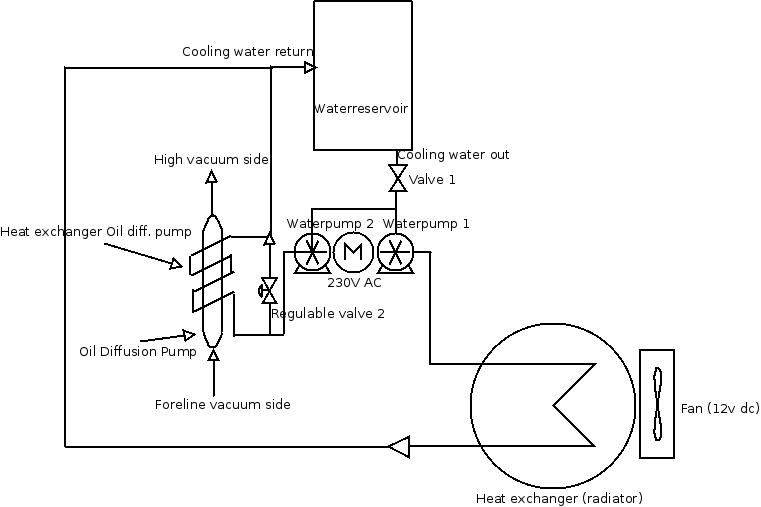 Image 30: Layout
cooling system for oil diffusion pump (© FRS 2014)
Image 30 shows the layout of the cooling system for the oil diffusion pump: A waterreservoir is gravity feeding two waterpumps, driven by one electric motor (230V AC). Gravity feeding means that the reservoir is placed at a higher level than the pumps, as this keeps the pumps permanently filled with water (dry running not allowed). Between the reservoir and the pumps is a valve (No. 1) to shut off the reservoir (leakage prevention when not in use) and a T-connector. The outlet of one of the two pumps is connected to the main heat exchanger (the car radiator), which is air cooled by an electric fan (12V DC) with speed regulation by a temperature controller, which reads the temperature in the coolant outlet of the main heat exchanger by means of a thermistor. The outlet of the main heat exchanger is connected to the water reservoir. This is the primary circuit of the cooling system The outlet of the second one of the two pumps is connected to a double connector (Y-connector) of which one outlet is connected to a regulable valve No. 2 that returns the water back into the reservoir and the other outlet is connected to the inlet of the heat exchanger for the oil diffusion pump of which the outlet is also connected to the reservoir. This is the secondary circuit of the cooling system Regulable valve No. 2 acts as a bypass and permits to regulate the flow through the heat exchanger of the oil diffusion pump. The flow size of the regulated valve No. 2 and the diameter of the tube that runs from the Y-connector through the regulated valve into the resevoir should be determined experimentally in order to find the correct tunable cooling flow required for the oil diffusion pump when in full operation. From experience it is known that an oil diffusion pump (Edwards Diffstak 100/300C) with an oil filling of 125 ml, a heating capacity of 650 W and a pumping capacity of 530 l/s requires a roughing pump with a pumping speed of > 4 m3/h and has a cooling water flow of 60 l/h at 20°C. Our Alacatel 6063 oil diffusion pump is a less powerful unit with less heat capacity and therefore will even require less cooling water per time unit. The cooling system as described for our system is therefore quite overdimensioned, which is on purpose because it is also needed in another project. For the temperature controller a ready made module was imported from China, since this is easier and cheaper (but takes longer) than constructing one in the workshop. It operates on the same 12V DC source which powers the fan and the relay can switch 14V at 20A. The switching temperature can be set at any value between -50 to +110°C. The accuracy is ± 0.1°C, the resolution is also ± 0.1°C and the refresh rate is 1 second. The sensor is a watertight encapsulated NTC resistor. Image 31 shows the module.  Image 31: Temperature
controller (Source:
Supplier, China)
The temperature controller has been set at a switching temperature of 45°C, i.e. the fan is switched on when the temperature of the cooling fluid exceeds 45°C. The chosen temperature is arbitrary but with a sufficient difference from ambient temperature to prevent the fan from running constantly. With the chosen temperature it is secured that the fan operates only when it is really required. For relatively short runs of the diffusion pump it is expected that the fan runs only minimally due to the fact that the total amount of water in the system is about 50 liters, which will permit 1000 kcal to be dumped into the cooling system before the fan will be activated. This amount of heat equals 120 Wh of energy. The chosen system of temperature control and regulation is cheap (< 10 EUR) but rather coarse with a large hysteresis. For my purposes with the large water buffer this is quite OK. Those who prefer a more fine tuned temperature control should e.g. use an Arduino programmed with a PID temperature control program with PWM output and a relay for switching the power load (fan), eventually completed with an LCD display. Total estimated costs about 35 EUR. Turbomolecular Pump A better alternative for an oil diffusion pump, though more costly, is a turbomolecular pump (TMP). A significant difference between oil diffusion pumps and TMPs is the fact that turbomolecular pumps are better in pumping particles with high mass and oil diffusion pumps are better in pumping particles with low mass. The advantages of a TMP are ease of operation, long life and oil-free operation. Oil-free operation, however, applies only to TMPs fully equiped with magnetic bearings. Older TMPs have minimally one oiled bearing at the bottom and (while rotating at an extremely high speed) oil mist may be distributed into the vacuum system. The turbopump is a molecular pump with rotors of turbinetype blades and pumping channels; the rotor blades are running between corresponding blades of the stator with a circumferential speed of the same order of magnitude as the mean particle speed of approximately 300-400 m/sec. In order to achieve that speed the rotor blades need to rotate at a speed of 50,000 to 90,000 rpm. Consequently, the smaller size TMP's rotate at the higher speed and the larger size TMP's at the lower speeds. The high speed of the rotors develop frictional heat and in order to dissipate the frictional heat TMPs are either water or air cooled. TMP's require an electronic driver/controller, a DC power supply and a corresponding cable between TMP and driver. Complete sets of TMP, driver/controller and cable can be found as used (second hand) sets for prices ranging from approx. € 1,000 up to € 3,500. Individual components are usually much cheaper but it can be difficult to locate the appropriate cable. Most TMP's will require an oil change every two years and bearings are a weak point and costly to replace. Maintenance schedules by TMP manufacturers mention periodically cleaning of the pump unit by partially immersing (see the manual) in Freon® or Frigen®, both tradenames for the same chlorofluorocarbon also known as Trichlorotrifluoroethane, or 1,1,2-Trichloro-1,2,2-trifluoroethane or CFC-113 and legally outphased since 2010 because of causing ozone destruction in the atmosphere. Unfortunately no good alternative exists for this inflammable, degreasing compound. Image 32 shows a typical example of a cut-open model of a turbomolecular pump. This model is a floor standing model and care should be taken not to exceed the maximum permissable load on top of the pump (here: typically < 50 kg) when attaching a vacuum chamber and/or other components. 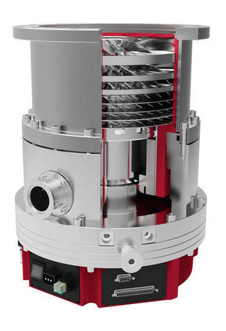 Image 32: Typical
example of a TMP (Source: Supplier)
More information about TMP's can be found in reference 6. Agilent Turbo-V 81-M The turbomolecular pump that we have available for our Fusor is an Agilent Technologies (formerly: Varian) Turbo-V 81-M Turbo-Drag Hybrid Pump (image 33 and 34). 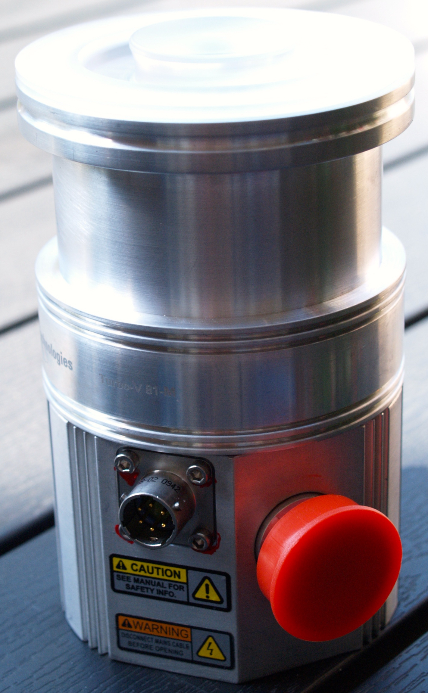 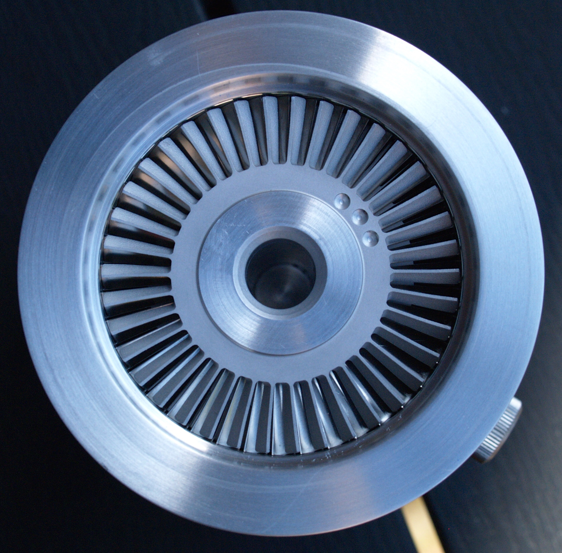 Image 33 and 34:
Agilent Turbo-V 81-M Pump; front and inlet turbo blades (© FRS)
This particular pump was built in 2012 by Agilent Technologies, factory released on 29 October 2012 (image 35 and 36), as type EX 969-8901, serial number IT12431029. The pump is operated with a 3 phase electric motor at 60 - 76V AC (nominally 76V AC) with a frequency of 1350 Hz. The maximum power rating is 100W. The original list price of this TMP is $ 4,912.07 ex taxes but it was bought in an auction for € 126. 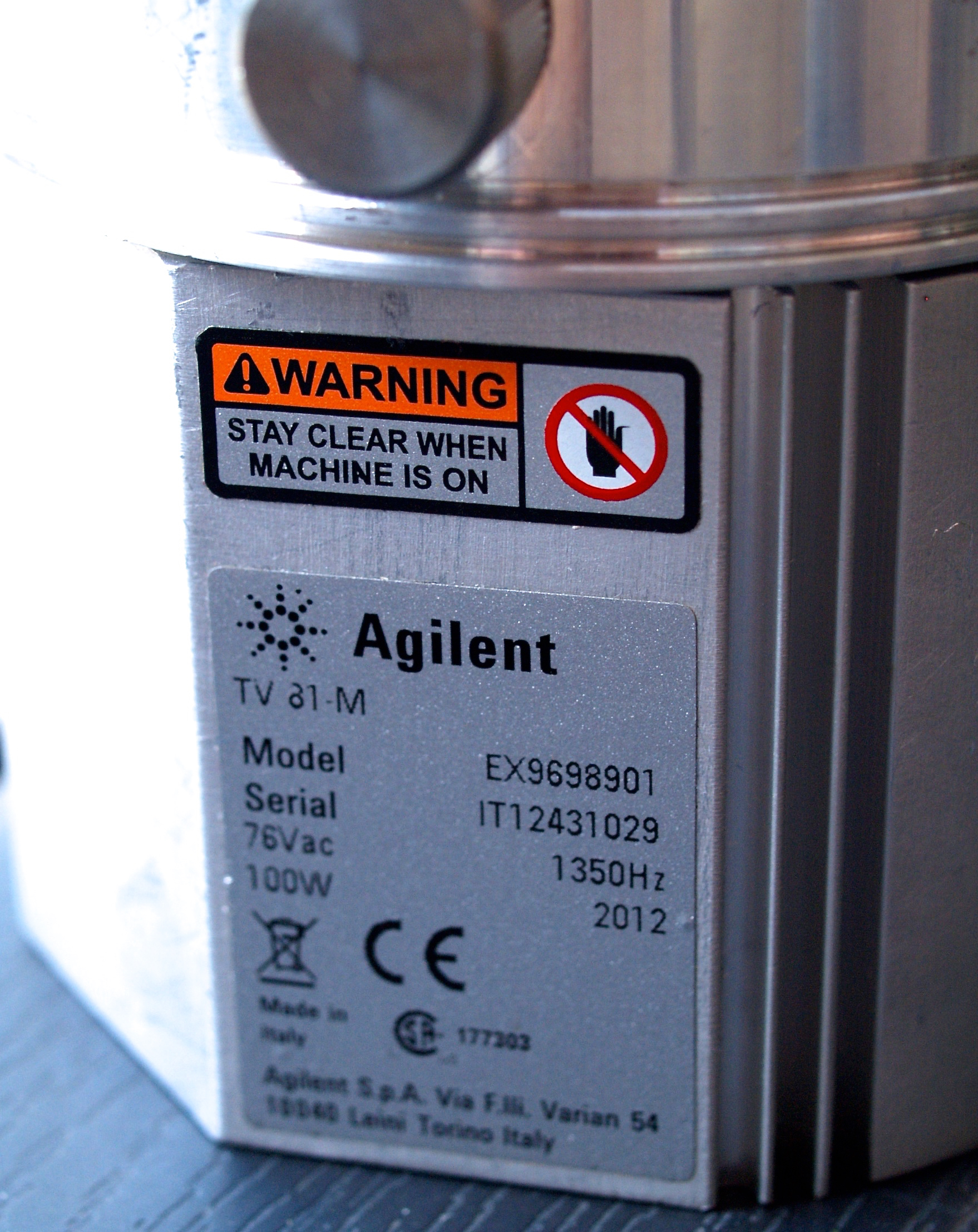 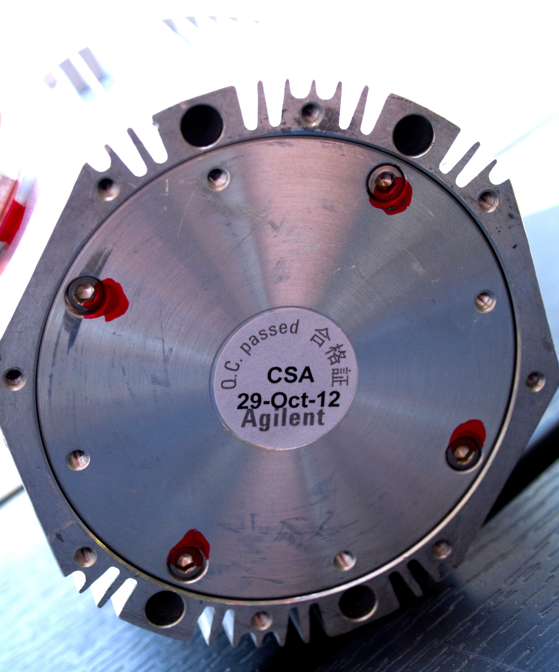 Image
35 and 36: Turbo V 81 M; ID and QC factory release (© FRS)
The Turbo V 81M Turbo Pump consists of a high frequency motor driving a turbine fitted with 9 bladed stages and 3 Macrotorr stages. The turbine rotates in a counterclockwise direction when viewed from the high vacuum flange end. The turbine is made of high-strength aluminium alloy, machined from a single block. The Macrotorr stages are in the form of three discs. The turbine rotor is supported by permanently lubricated high precision ceramic ball bearings installed on the forevacuum side of the pump. The ceramic bearings have a typical MTTF of > 200,000 hours, which equals 22.8 years of continuous running when not damaged by vibrations or dirt intrusion. The static blades of the stator are made of stainless steel. These are supported and accurately positioned by spacer rings. The Macrotorr stators are in the form of selfpositioning machined discs with pumping channels and an opening restricted by the corresponding rotor discs. These are made of aluminium alloy. The ultimate pressure that can be obtained is 3.75 x 10⁻¹⁰ Torr or 5.0 x 10⁻¹⁰ mbar; it has a compression ratio for Hydrogen of 7.0 x 10³, a pumping speed of 50 l/sec (180 m3/h) and it has a weight of 5 kg. Maximum turbo blade speed is 80,000 rpm and cooling is at ambient temperature. The pump can also be water cooled or air cooled: in the first case the customer can use a dedicated external plate made of nickel-plated brass, in the second case an external optional fan is available. The foreline flange is KF 16 DN and the inlet flange is ISO 63 NW. The vent valve port has an internal thread of M8x1.25. The total height of the TMP is 144.6 mm and the width is diam. 84.0 mm. A manual for the Turbo V 81M Turbo Pump can be found with reference 7. During normal operation, the motor is fed with a voltage of 54 Vac three-phase at 1350 Hz (max). To reduce losses during start-up to a minimum, the frequency increases according to a ramp with a higher initial voltage/frequency ratio. A thermistor sensor is mounted near the upper bearing to prevent the pump from overheating. This particular TMP can start pumping at pressures as high as 18 mbar, though it is advised to start pumping at lower pressure. A protection switch tripping at 5 mbar is advised for switching the pump off when the pressure rises above 5 mbar. Switching off the turbo pump as such may cause problems when the turbo pump is connected to an oil based foreline pump such as a rotary vane pump. Backflushing oil vapours from the foreline pump directed in a flow towards the vacuum chamber (at a lower pressure) may enter the turbo pump and cause damage to the pump. Therefore it is required immediately after switching off to vent the turbo pump with a dry gas (e.g. nitrogen) before the rotational speed is at 20% of the maximum pump speed (for our turbo pump about 16,000 rpm). A protocol to enable the venting process could be as follows:
A description of an automated vent valve control system can be found on the Control Systems webpage. The following power controllers can be used with this pump:
The pin layout on the TMP for connection to a controller is as shown in image 37: 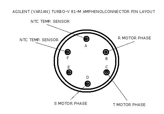 Image 37: pin layout for Amphenol connector on Agilent Turbo-V 81-M Pump (© FRS 2015) The box mount circular connector on the turbo pump bears the product code: 97814 A8113-10-6P-SP-M9-02 0942. The advantage of a turbo drag hybrid TMP is that the pump has a second drag stage, which more or less acts like an Auger with a fine pitch, and this principle increases the compression ratio of the overall TMP. Because at the second drag stage no rotor blades are involved, the pump accepts a higher starting pressure. The rational for the higher starting pressure is the fact that in TMPs, revving at very high rpm, the rotor blade tips have speeds exceeding supersonic. In a higher particle density these hypersupersonic blade tips start burning up by friction with the gas particles, which may release tremendous powers from rotational energy, possibly ripping the TMP off its mounting bolts. A higher starting pressure with a turbo drag hybrid TMP permits a lousier foreline vacuum and enables use of diaphragm vacuum pumps as a roughing pump, creating a very clean vacuum system. Another possibility for an oilless system is using a dry scroll vacuum pump as roughing pump. An open question still remains. How do we know that a chosen foreline pump matches a specific turbo pump? A general rule that is applied to answer this question, is as follows: Sforeline ≥ 20S / K
where Sforeline = pumping speed of the foreline pump, S = pumping speed of the turbo pump, K = the maximum compression ratio of the turbopump for a given gas (i.e.: process gas) at the operating foreline pressure. Our Trivac S2A foreline pump has a nominal pumping speed of 2.3 m3/h; the pumping speed of the turbopump is 180 m3/h and the compression rate of the turbo pump is for hydrogen 7 x 10³. Substituting in the formula we get: 2.3 ≥ (20 x 180) / 7x 10³, which is true because the right term yields 0.53 and that is four times less than the left term! For our Edwards E2M1.5 two stage rotary van pump the pumping speed is 1.5 m3 /h and therefore this pump also qualifies as a foreline pump in combination with the turbo pump. This means that we can use either the Trivac S2A pump or the Edwards E2M1.5 pump without any problem as a foreline pump for the Varian Turbo-Drag Hybrid pump. Varian TV 70 Controller Lacking the appropriate V 81 Controller for the Turbo V 81M Turbo Pump, a V 70 Controller was acquired for a very low price. The low price (€ 80) was justified by the fact that the controller apparently was literally cut out a working environment as demonstrated by the cut off wires shown in images 38 and 39:  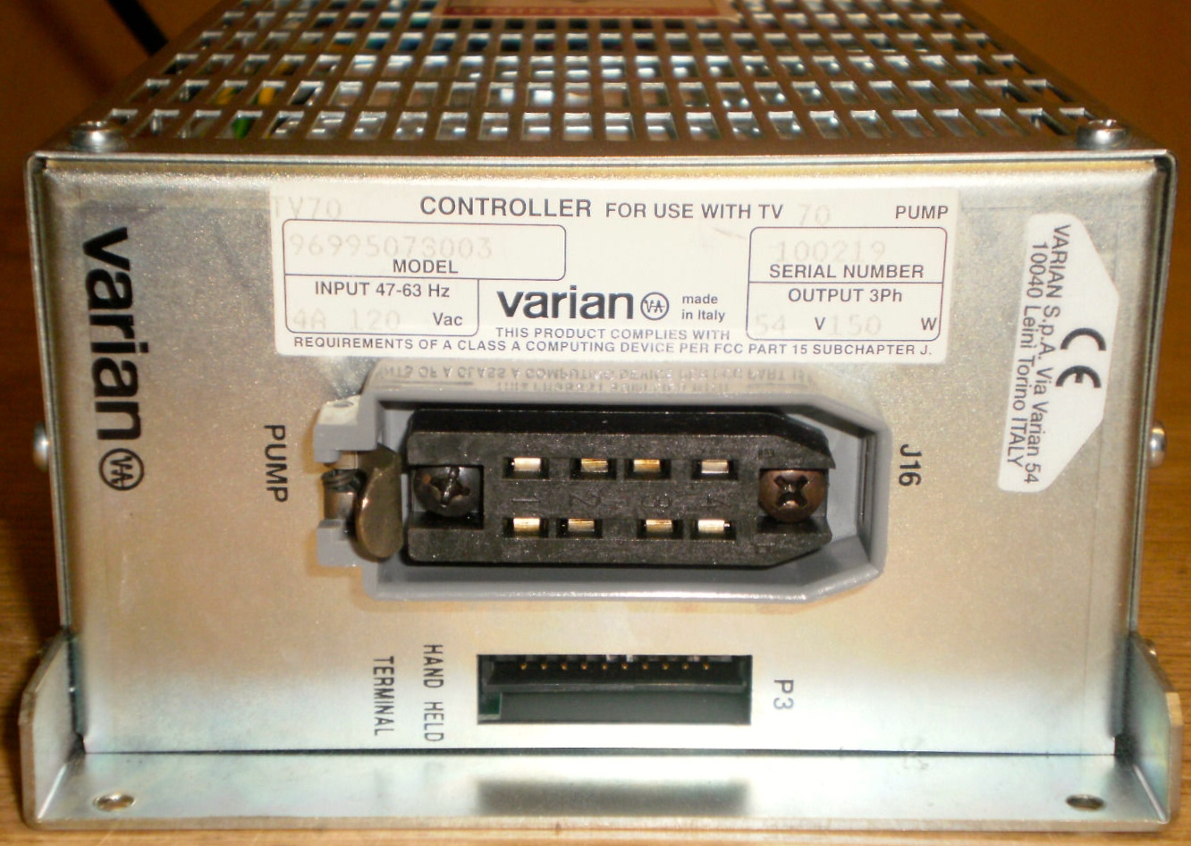 Image 38 and 39: Varian TV 70 Controller, back and front connector sides (source: 6450oskar) The Varian TV 70 model 969-9507-3003 controller has a 120V AC, 4 A input (but can be set to 230 V AC) and a three phase 54 V AC output at 1250 Hz. The output specifications seemed also suitable for the Turbo V 81M Turbo Pump and it was therefore worthwhile to do a test with this controller connected to the V 81M pump. Moreover, we found a description of an Agilent Varian Controller Adapter Kit TV 70 - TV 81, with part number 9699164, which indicates that a Turbo V 81 pump apparently can be operated with a Turbo V 70 Navigator controller (see reference 8). However, prior to testing a few issues needed to be sorted out:
The first issue is rather simple to resolve: download the manual from reference 9 and look up functions and connecting diagrams. The second issue is more difficult and requires more time and setting a searching profile on eBay. In particular finding a hand held remote controller terminal may be difficult. The V 70 controller does not have the optional RS232 serial communication port and that makes communicaton with the controller through a PC with help of a serial communication program impossible. However, direct communication via the P1 In and the J2 Out port will be possible and the construction of a terminal panel to be connected to P1 and J2 can be found on the Control Systems page. Image 40 shows a controller with an integrated terminal, which consists of a microprocessor for data communication and processing, four push buttons and a backlighted 16x2 characters LCD display. 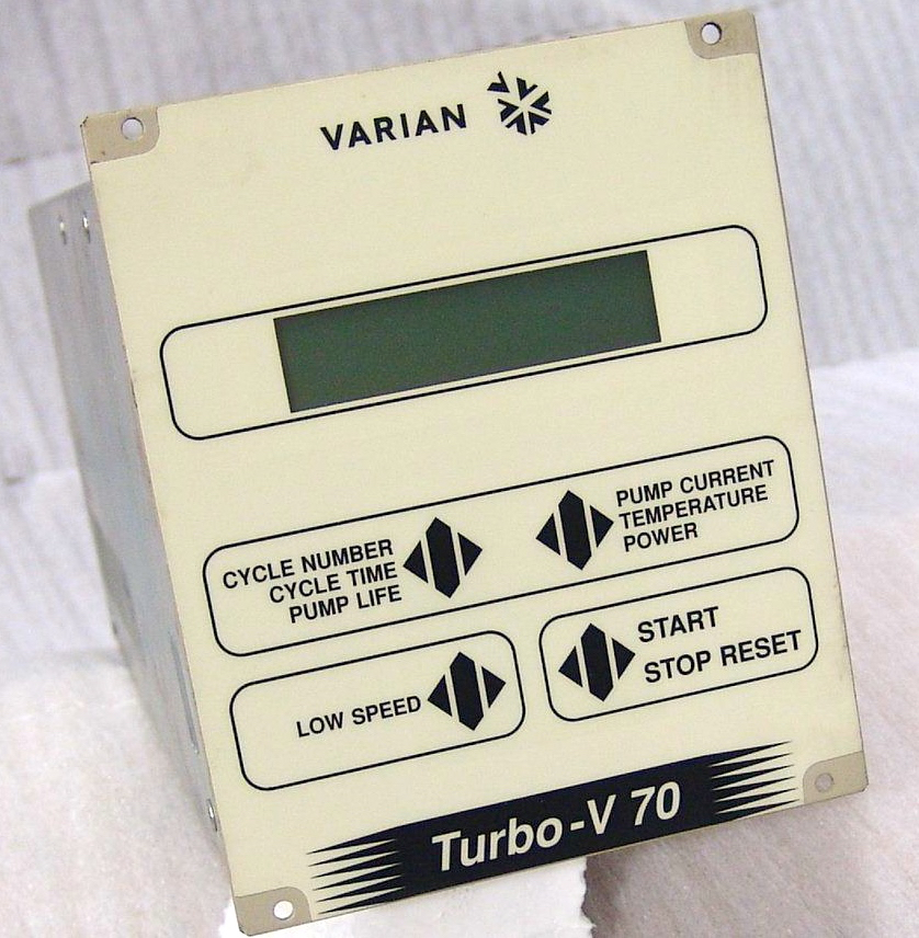 Image 40: Turbo-V 70
Controller with integrated Terminal
The third issue requires mimicking a turbo pump connected to the controller and operating the controller. Mimicking a turbo pump is done by connecting three high wattage resistors in a triangle configuration to the turbo pump connector on the controller and powering it up. Required for this test are a true RMS digital voltmeter or multimeter (DVM or a DMM), a Dummy load: 3 x 48Ω, 50 W each or 3 x 78Ω, 50 W each and a Potentiometer 50 KΩ, 1/4 W minimum. Please note that a true RMS voltmeter is required here because we will measure a non sinusoidal variable frequency AC voltage, which on "standard" (averaging) DVMs will be read as an approximately 0.68 times or 32% lower value. The reference values as provided in the manual by the manufacturer of the controller are RMS values and by using a "standard" DVM for measuring we might get the impression that the controller is faulty. More details can be found on the Experiments and Results page. Buying a used turbomolecular pump Searching the internet (eBay, surplus dealers or specific vacuum technology companies) shows that many used turbomolecular pumps are being offered today, whereas oil diffusion pumps become more and more obsolete. Many fusioneers feel attracted to turbomolecular pumps due to the clean operation and the fast way a high vacuum is obtained with the flick of a switch. However, turbomolecular pumps need a turbo pump specific controller annex power supply and a similarly specific connection cable. Finding a complete set usually means paying a high price and obtaining only the pump usually means a steep learning curve in constructing or converting a controller, not to mention finding a cable and /or connectors. Moreover, the risk exists that the turbomolecular pump was discarded due to malfunction. The bare fact that turbomolecular pumps are highly complex mechanical apparatuses contributes to the risk of buying a pump that needs a costly overhaul. Contrary to the complexity of a turbo pump is the relative simplicity of an oil diffusion pump, operating without any moving parts and with the only possible malfunction because of a defective heater element, which is usually relatively easy and cheap to replace. Testing a turbo pump for functionallity outside a high vacuum system is not easy. Usually it is said that the pump rotor should turn freely and smoothly and not come to an abrupt halt. This is a very subjective way of testing a turbo pump with a result that leaves lots of space for differences in interpretation. Performing this test is always done wearing protective gloves (rubber, vinyl, polyurethane, not powdered!) or with the rubber eraser at the end of a pencil. Using bare hands will leave fingerprints on the top rotor blade and this may lead to rotor unbalance, which will damage bearings. This may seem exaggerated but a simple example calculation demonstrates the effect: According to literature a fingerprint leaves a residue with a mass (i.e. in our case an unbalance load) of about 50 µg (or more precise 0.000049 g); the turbomolecular pump rotates at 80000 rpm and the fingerprint mass is at a distance of 7.5 cm of the centerline of rotation. An equation for calculation of the radial force on the rotor axis was found in reference 10 as Flbs =
0.062 x (rpm/1000)2 x U gm.In.
when we adapt this formula for kg and cm units by applying the conversion factors for lbs to kg (0.45359237) and for inch to cm (2.54) we will get: Fkg x
0.45359237 =
0.062 x (rpm / 1000)2 x 2.54 x U gcm
orFkg =
0.347 x (rpm / 1000)2 x U gcm
where:U = unbalance load in gcm 1 gcm = 1 g of mass at 1 cm of the radius from the centerline of rotation Fkg = radial force on the rotor axis in kg. For our example the radial force on the rotor axis by the fingerprint is Fkg
= 0.347 x (80000/1000)2 x 0.000049 x 7.5 = 0.666 kg, which
equals 666 gram
The result is quite exorbitant and it even may add to the (always present) existing unbalance (residual unbalance after dynamic balancing of the rotor) causing severe vibrations, which therefore absolutely should be avoided. Because unbalance is a rotating load, the bearing’s inner race is zone loaded. This is a different type of loading compared to most of the other force sources. A general rule is that a 10% load increase on a bearing decreases the bearing life with 25%. The most common type of failure in a turbomolecular pump is therefore bearing damage and used turbo pumps usually come with faulty bearings. The bearings are expensive to replace as they are specially constructed, high speed, high precision bearings, lubricated with a special lubricant and sometimes having ceramic balls. It is not uncommon that the price for such a single bearing exceeds 400 to 500 EUR and a complete pump revision set may exceed 800 EUR, labour excluded. Therefore fusioneers sometimes try to find cheaper replacement bearings for replacing faulty ones. You may be lucky with your cheap replacement bearing(s) though in most cases the cheaper bearing(s) will also be gone after a short while of rotating. The reason of failure is that during ramping of the turbo pump motor from zero speed to top speed resonances will occur, which resonance point is also called the critical speed for a turbo. The bearings that support a rigid rotor with an effective mass, provide a restoring force and act like springs. Any system with an inertial mass and restoring force or stiffness has natural frequencies. When an external driving force appears, such as the unbalance force, and it has the same frequency as one of the natural frequencies, resonance is created. Bearings behave like springs, since they apply a restoring force to set the rotating object back to its original position. The spring force constant is in bearings called the stiffness and it is an important parameter to consider. Your new, cheap bearings may have a stiffness totally different from the original manufacturer's bearings and arrive earlier at the critical speed during ramping to the turbo's high speed. A trick could be to increase ramping speed in order to pass the critical speed fast, but bearing damage will still build up and the moment will arrive soon that the bearing literally breaks down because one of the races, usually the inner race, will be torn apart. Testing a turbo molecular pump by powering up a free-standing turbo pump may cause a severe danger to your health as well as ruining your workshop. When the turbo pump is not fastened to a heavy support, it will be launched with an tremendous kinetic energy when the pump crashes. Crashing may occur due to sudden bearing failure and/or cracking or breaking of (a) rotor(s). Imagine here that the inner race of a bearing brakes while rotating, which will cause an immediate loss of the restoring force for setting the rotors back to the original position. The forces from residual unbalance will now cause the rotors to crash into the stators. The sudden blockage of the rotors rotating at a speed of up to 80.000 rpm will suddenly release the kinetic energy of the rotating mass and launch the pump into the work space. It may hit you (in the worst case killing you) or equipment in your workshop (and destroy it) or hit the wall (and bounce off to change direction) and create a lot of mess. This is not what you would like to happen and therefore always operate a turbo pump when it is securely fastened to a heavy support, even when only testing for half a minute to see if it works. It is not possible for me to go into details, but scientific research with ultra-centrifuges in the late sixties has learned me that a launched rotor rotating at 100.000 rpm was burried up to 30 cm deep into a concrete wall. No further comment! Vacuum System Components A disadvantage of working on a low budget is the diverse collection of different types of equipment that finally are part of the complete system. At the same time the advantage is that for a low price sometimes quite some "jewels" are collected. Clamps Clamps are used for connecting a vacuum part to another vacuum part. Because we mainly make use of parts with KF flanges we restrict our description of all the different types of clamps that exist to these KF flanges only, as used in our system, and to clamps for the ISO-DN flanges which are used for connecting larger sized vacuum parts. For ultra high vacuum (UHV) systems, usually Conflat flanges are used, which have seals made of copper (or other metals). A Fusor is not an UHV system but operates in a medium high vacuum range, for which KF flanges and centering ring seals with Viton O-rings are quite suitable. For connecting vacuum parts we make use of centering rings with viton seals of an appropriate size (image 41) and clamps which press the parts together onto the sides of the Viton O-ring seal, thus creating a vacuum tight connection. 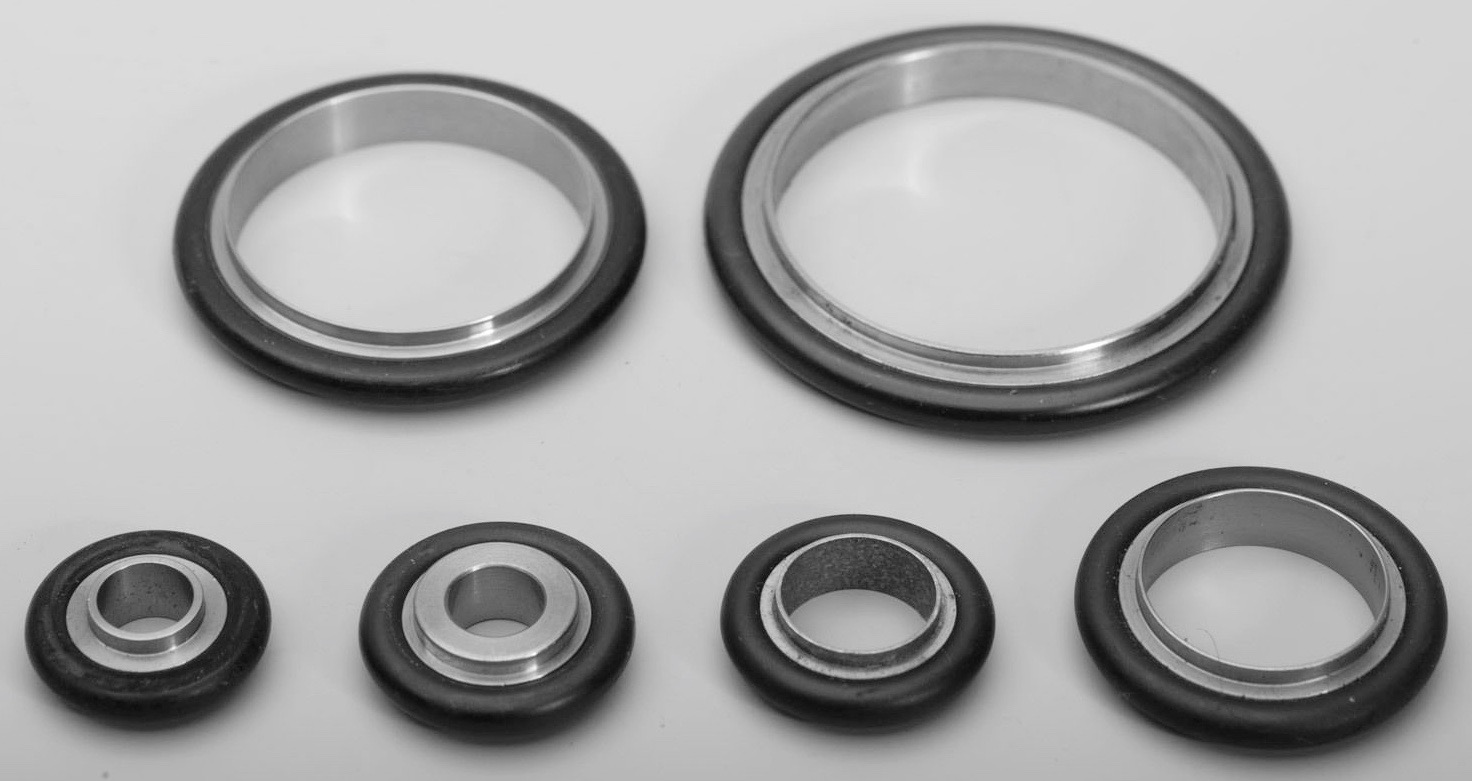 Image 41: centering rings in different sizes (source: supplier) For flange diameters between 10 and 50 mm we make use of clamps that surround both the (tapered) flanges and which will force the flanges together by tigthening a wing nut (image 42): 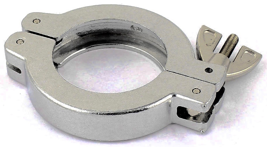 Image 42: KF clamp (source: supplier China) For (ISO-DN) flanges ranging from 63 to 630 mm we make use of either ISO-K double clamps (image 43) or ISO-F (image 44 and 45) clamps, depending on the flange type: 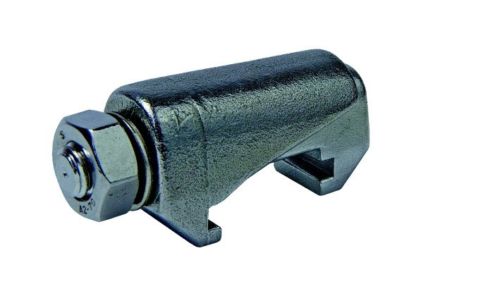 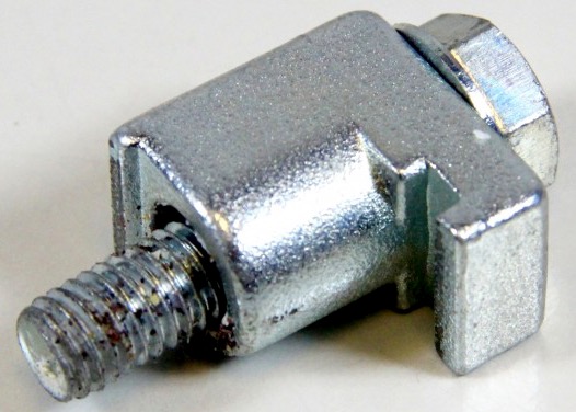 Image 43: ISO-K double clamp Image 44: ISO-F single clamp 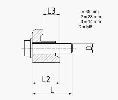 Image 45: ISO-F clamp dimensions The ISO-K and ISO-F clamps will be used for the larger size flanges and they are available in three types for the different flange size ranges. For ensuring a vacuum tight connection the same type of centering rings with Viton O-rings is used, except that an extra closing ring has been placed on the outside of the centering ring (see image 16 for a large size centering ring). The ISO-K flanges have a groove to which the clamp is attached, like the top flange on the turbo pump of images 33 and 34. For an identical contra-flange the double clamp of image 42 will be used. The ISO-F flange (without a groove but with holes instead) is shown in images 17, 18 and 58 and these are in combination with an identical contraflange connected by standard M8 bolts and nuts. In case of a mix of ISO-K and ISO-F flanges to be connected, the ISO-F single clamp of image 44 will be used, either single or double depending on the situation. The actual ISO-F clamp of image 44 is intended for fixation of an ISO-K flange to an ISO-F flange with a threaded M8 hole. When the hole is not threaded, than the bolt is replaced by a longer M8 bolt or a threaded rod with nut and fixation takes place with a nut on the opposite side. When we want to connect two ISO-K flanges to either side of the buterfly valve of image 58, than we place an ISO-F clamp on each side fastened by an even longer bolt and nut. The torque to be applied to the bolt and nuts for fixing flanges in the ISO-K dimensions from DN 63 to DN 250 is 12 to 16 Nm and for sizes from DN 320 to 630 it is 20 to 26 Nm, see reference 11). In our vacuum system we mainly use four (image 58) and eight bolt flanges (images 17 and 18), which require tightening according to the following schedule:
Tubing For "roughing" the vacuum chamber, the foreline pump is directly connected with the vacuum chamber by means of a flexible, stainless steel vacuum tubing with KF 25 NW connectors at both ends (image 46): 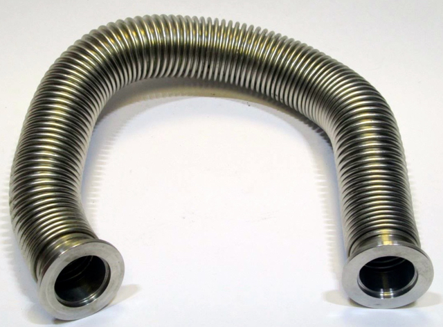 Image 46: Flexible
tubing KF 25 NW, 400 mm length (© SPS-Parts, Germany)
The inventory of vacuum parts counts two flexible tubings with KF 16 NW flanges and 400 mm length, two flexible tubings with KF 25 NW flanges and 400 mm length and two flexible tubings with KF 40 NW flanges and 100 mm length (image 47). 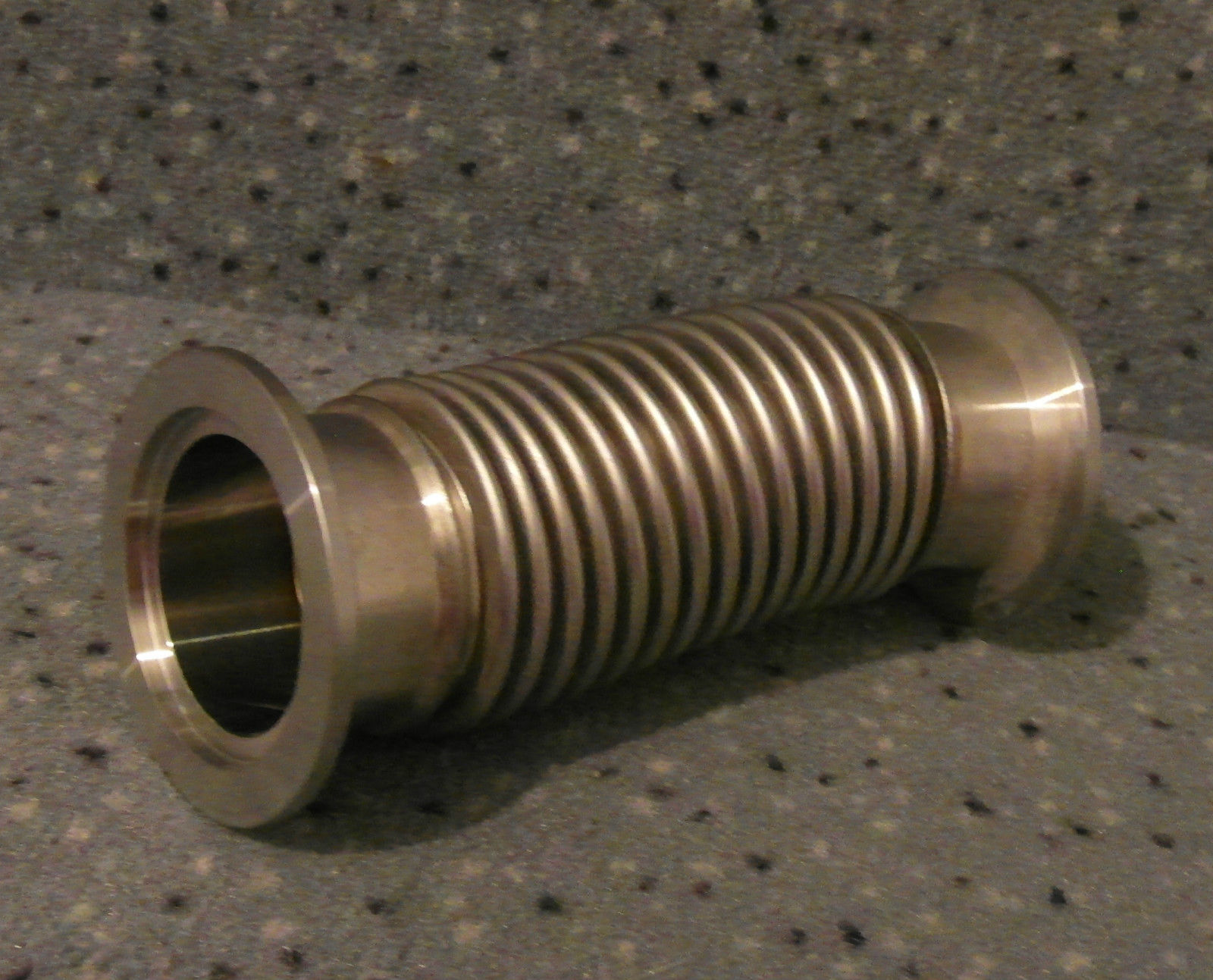 Image 47: flexible
tubing KF 40 NW, length 100 mm (© supplier, Germany)
Crosses, Tees and Bends The vacuum line has a number of crosses (4-way junctions) and tees (3-way junctions): 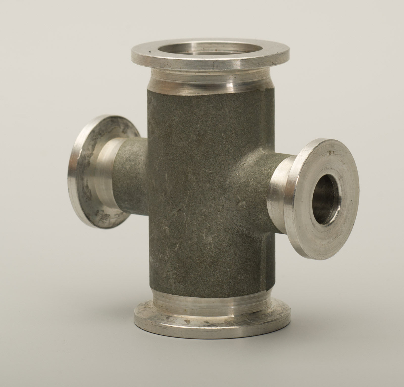 Image 48: Edwards
cross (4-way junction 2 x KF 25 NW, 2 x KF 16 NW (© Supplier, GB)
The vacuum cross junction in image 48 is the cross that is mounted on top of the foreline pump. The main vacuum goes straight on through the KF 25 NW connectors direction diffusion pump and vacuum chamber short cut. One KF16 NW connector is connected to the Thermocouple gauge for measuring the foreline pressure; the other KF 16 NW connector is connected to an electromagnetic air admit valve for flushing air into the system. A brand-new 3-way junction that has been acquired (auction EUR 13.49) is a stainless steel Leybold-Heraeus 25/25/25 T-piece with three KF 25 NW connectors (image 49): 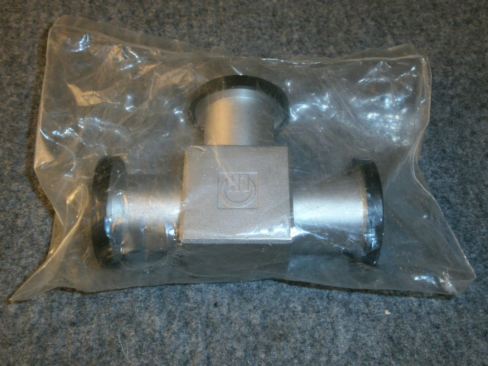 Image 49:
Leybold-Heraeus 3-way junction KF 25 NW (source: Supplier)
The T-piece from image 49 will be mounted to the vacuum chamber as shown in image 1, the schematic layout of the vacuum system. Another 4-way cross is further required for mounting between the vacuum chamber and the foreline valve by means of the flexible tubing from image 45 and the 90° angle connection connected to the foreline vacuum valve for the diffusion pump. Also in the collection of available parts are a T-piece with KF 40 NW flanges and a 90º circular bend also with KF 40 NW flanges (image 50). 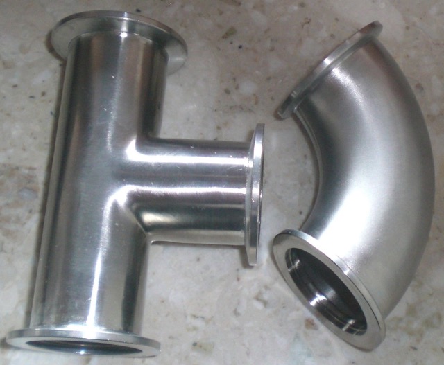 Image 50: 3-Way
Junction and 90º Bend, all with KF 40 NW flanges (source: Supplier)
Switches Vacuum switches (image 51) have a sensor that has been preset to a chosen pressure at which an internal relay switches. Their function is to prevent damage to components, such as high vacuuum gauges which should not be exposed to ambient pressure, or to protect oil diffusion pumps by closing valves when a roughing pump suddenly fails while the system is under high vacuum. 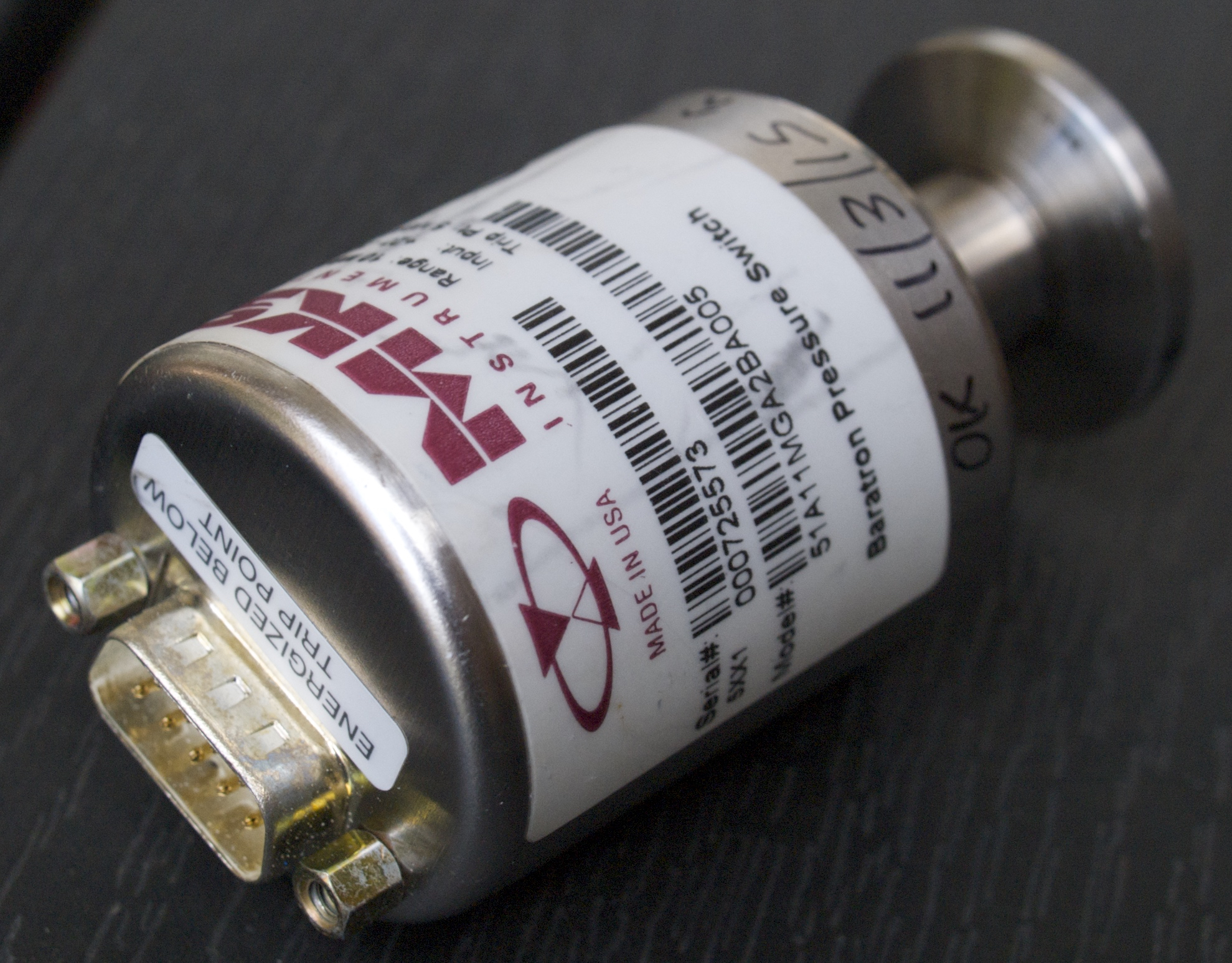 Image 51: MKS Type
51A Vacuum Switch with KF 16 NW flange (© FRS 2015)
The MKS Baratron vacuum pressure switch with product number 51A11MGA2BA005 and serial number 000725573 operates in the range from 1 to 10 mbar and trips at 5 mbar (3.8 Torr). The relay is energized when the pressure drops under 5 mbar. When the switch is not powered by the power supply (20 - 30 V DC at max. 30 mA) it is in the "normal" state, i.e. the normally closed contact (N/C) is closed and the normaly open contact (N/O) is open. Consequently, a pressure higher than 5 mbar (or a power supply cut off) sets the relay to its normal state. A trip point of 3.8 Torr is too high to protect a diffusion pump because these must be operated at pressures below 0.5 Torr, but for protection of the high vacuum gauge this trip point will do. The vacuum switch is to be connected in such a way that both the roughing vacuum valve and the foreline vacuum valve will be closed when the pressure in the system exceeds 5 mbar (approx. 4 Torr). Another way to use this vacuum switch is in combination with a turbomolecular pump. Our pump is a turbo drag hybrid pump that permits starting at a pressure of 18 mbar or lower. Therefore these pumps can be used with a diaphragm vacuum pump in the foreline, yielding a very clean high vacuum. Should we instead use a rotary vane pump in the foreline than the possibility exists that backstreaming of oil contaminates the turbo pump, especially when the pressure in the high vacuum part of the system suddenly rises due to a leak or component failure. In order to protect the turbo pump for such a situation, a pressure switch is connected to the system that operates a solenoid operated NC vacuum valve between the foreline pump and the turbo pump. When the pressure in the sytem rises above 5 mbar, the vacuum valve closes, separating the foreline pump from the turbo pump. The MKS Type 51A vacuum switch is connected to a power supply and to attached components through a 9 pin "D"-type connector (reference 13). The layout of the pins in the "D"-type connector is as follows (image 52 and table 4): 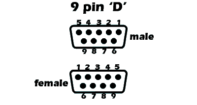 Image 52: Pin Layout
9-Pin "D"-Type (as seen from the
wiring side)
Table 4: Pinout of
the 9-Pin Type "D"-Connector
Manual Valves The vacuum system has one manually operated high vacuum valve (image 53): 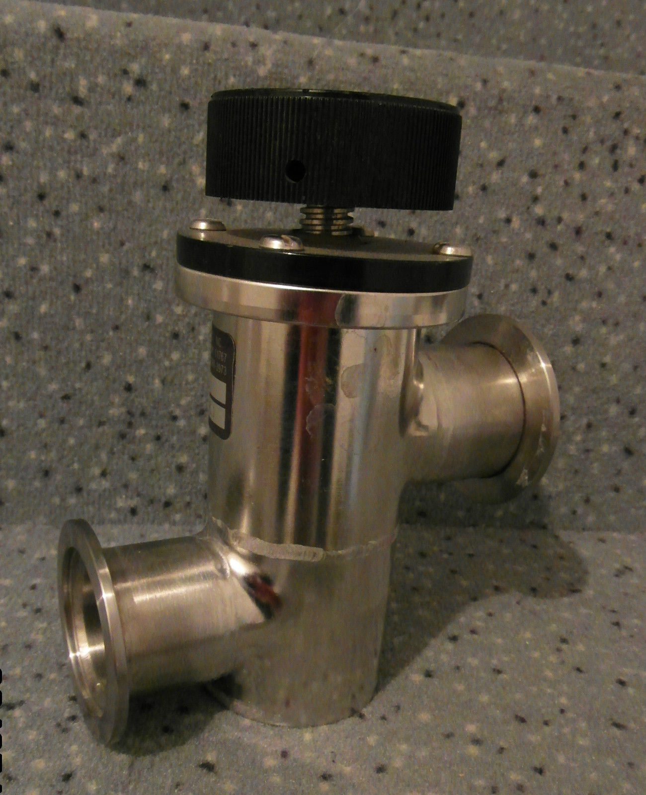 Image 53: Key High
stainless steel bellows valve KF40
The manual valve is a Key High bellows sealed, stainless steel valve, type SL-150-KN with DN40NW flanges. Original list price USD 375.00 but it was obtained in an auction for EUR 21.72. Electromagnetic Valves Solenoid In-Line Valve The mechanical pump ventilation valve is a 24V DC, 8W, NC (normally closed) electromagnetic vacuum valve, manufactured by Bürkert, with DN10NW flanges, was obtained in an auction for EUR 12.10 (image 54): 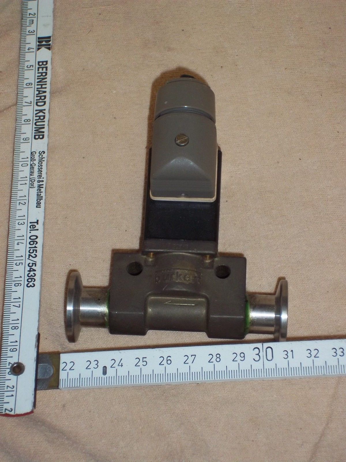 Image 54: Bürkert
KF16 valve
The Bürkert NC valve is used as a ventilation valve for permitting air into the vacuum system when it needs to be dismantled or opened for service. An electromagnetically operated valve is here very suitable as a venting valve due to its normally closed function, which is the more permanent situation for a venting valve, whereas it can be electrically powered from a distance for venting, which is an action usually of short duration. Of course, a hand operated valve is equally well suitable for venting purposes. For prolonged operational use of an activated solenoid valve it needs to be checked that the solenoid has an ED of 100%. Air Admit Valve For the vacuum chamber ventilation valve a BOC Edwards Air Admittance Valve will be used, type IPVA10EK, part numberC41733000, NC, 24V DC as shown in image 55: 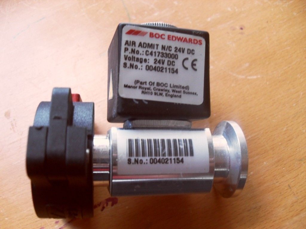 Image 55: BOC Edwards
KF16 Air Admit Valve
The BOC Edwards Air Admittance Valve, IPVA10EK, has DN10NW flanges and sells at EUR 361.00 but was obtained in an auction for EUR 1.50 (though without the electrical supply socket). Turbo Vent Valve Our ventilation valve for the turbo pump is a new Pfeiffer PM Z01 313 sealing gas valve (image 56; €35 on eBay). 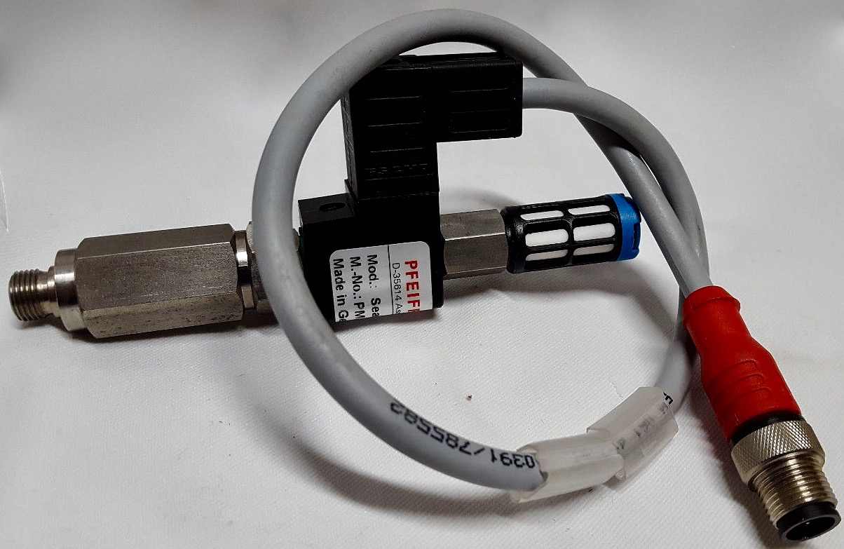 Image 56: Pfeiffer Sealing Gas Valve (Source: Supplier) The turbo vent valve has at one end a G1/8" screw mount fitting which should fit into the Varian turbo drag hybrid pump, though we will need to add a brass adapter connecting a Pipe Fitting 1/8" BSPP Female to a Metric M8 M8X1.25 Male (image 57). The other end of the valve has a fine inlet filter for ambient air (image 58), de facto a standard pneumatic silencer made by Festo as model U-1/8 2307. The function of the turbo vent valve is to prevent damage to the turbo pump bearings by particle ingress when ventilation to ambient air is performed. 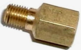
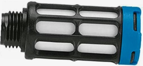 Image
57) Adapter 1/8" BSPP Female to M8x1.25 Male
58) Festo Silencer (Source: Suppliers)
The vent valve is normally closed (NC) and it is operated by applying 24V DC (2W power consumption) to a solenoid. When opened, the gas flow at atmospheric pressure is 17.5 to 20 sccm. The turbo vent valve comes with an integrated cable and plug. The plug, cable and solenoid connector (5-pin, M12x1) are of the ESCHA brand and the wiring diagram is as follows (image 59): 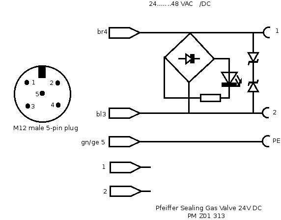 Image 59: Connector Schematic Pfeiffer Sealing Gas Valve PM 201 313 (© FRS 2017) The plug fits into a panel feedthrough connector of the same Escha brand, type FKFS4.5/M12, model number 8018405, which we found for USD 8 on eBay (image 60): 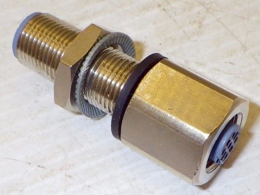 Image 60: Escha Panel Feedthrough connector (Source: supplier) The panel feedthrough enables to mount a permanent connector on the Fusor switch panel, which permits an easy disconnection of the turbo vent valve from the system. The wiring is connected to the male connector side of the panel feedthrough by means of circuit board valve socket contact pins e.g. as used for connecting Nixie tubes. The contact pins are soldered onto the three wires supplying positive and negative of 24V DC and mains ground to the turbo vent valve. The pins are suitable for fitting onto valve socket pins with a diameter ranging from 0.9 - 1.1 mm, which fully complies with the panel feedthrough pins diameter of 1 mm (Image 61). 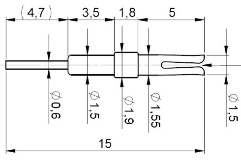 Image 61: Contact pin for 1mm diam. pins (Source: Supplier) Pneumatic Valves Foreline and Roughing Valves The foreline valve and the roughing valve are both pneumatically operated vacuum valves (image 62): 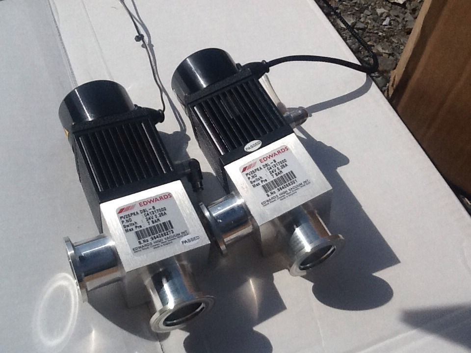 Image 62: BOC Edwards
pneumatic valves KF25
Both pneumatic valves are manufactured by BOC Edwards and they are models PV25PKA DBl_B with KF 25 NW flanges. Both valves were obtained in an auction for EUR 26.64 but have a list price of EUR 532.00 each. The model PV25PKA is a bellows sealed valve, suitable for 5*106 actions and with a reaction time of 20 ms to close. Similar to electromagnetic operated valves, which are normally closed, pneumatic valves are also normally closed by means of a spring. The pressure of compressed air forces the valve to open and to remain open as long as the pressure is maintained. The position of the valve is visually indicated by a pin, which rises up from the housing when the valve is open. Additionally, in either open or closed position the pin in the valve activates one of two microswitches, each rated at 24V, 1.5A AC or DC, for indicating the open/closed position of the valve on a switching panel. For reading the two microswitches a four wire cable will be needed. Both valves will be connected in such a way that they operate in tandem though with different pneumatic controllers, i.e. when the roughing valve is open, the foreline valve will be closed and vice versa. The reason for this is that when evacuating the vacuum system with the roughing pump, in order to obtain a minimum vacuum suitable for operation of the high vacuum diffusion or turbo pump, we prefer to do that by pumping directly at the vacuum chamber with the high vacuum pump isolated from the roughing pump. In the next step, when a sufficiently low pressure has been obtained of about 5 mbar, we open the forline valve and evacuate the system on the high vacuum pump side up to the high vacuum valve. When a total system pressure of lower than 5 mbar has been obtained we start the high vacuum pump and open the high vacuum valve, which has now more or less equivalent pressures on both valve sides and opens therefore more easily. For operation of the model PV25PKA pneumatic valves single acting pneumatic control systems are required. For extending the life of the PVPK valves the manufacturer recommends to put a flow restrictor in the pneumatic air supply line, e.g. preferably in the A or B orifices of the 5/2 controller valve (image 55 lower right part), with an opening of 1.2 mm dia. The flow restrictor will limit the opening and closing time of the vacuum valve. A different solution of flow restriction can be done with a regulated choke, inserted in the A and B orifices. The PVPK vacuum valves can be used with oiled or non-oiled air supplies (reference 14). High Vacuum Valve Instead of the planned linear gate valve an Edwards QSB63P butterfly valve with a list price of EUR 1740.00 was acquired in an auction for EUR 5.50. It appeared to be in an excellent condition and looked as new. The winning bidding was indeed a great opportunity to get hold of such a fine piece of equipment! The Edwards QSB83P (image 63, reference 15) is a high vacuum butterfly valve with ISO 63 flanges and it is made of type 304 stainless steel. It has a double action cylinder for pneumatically operating the valve and microswitches report the position of the valve, open or closed. The pressure range is from 10-9 to 3000 mbar (8x10⁻¹⁰ to 2250 Torr). The reliability is >1.5x10⁵ cycles. The pneumatic cylinder has two 1/8 inch connectors for 6 mm OD tubing; the recommended pressure is 2.8 to 4.2 bar. Each microswitch has a rating of 5A at 48V. 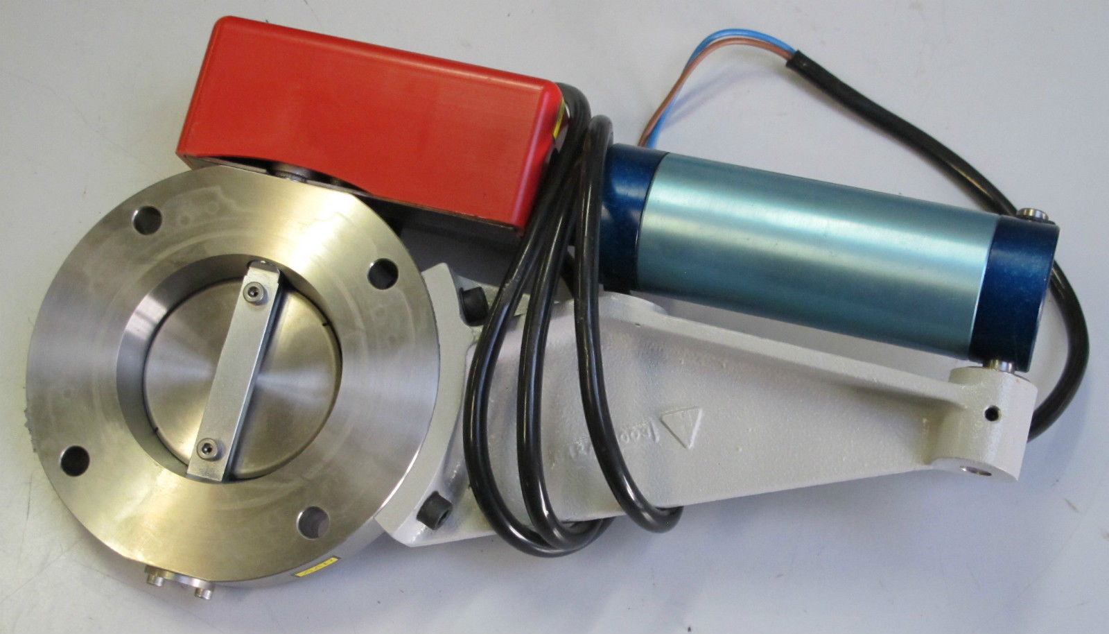 Image 63: Edwards QSB63P Butterfly Valve For a description of pneumatic control system for the pneumatically operated vacuum valves please go to the webpage "Control Systems". The complete vacuum system consists of one double action butterfly valve, to separate the vacuum chamber from the oil diffusion pump or the turbo drag hybrid pump, two single action vacuum valves, one foreline valve and one roughing valve, and two air admit valves. The air admit valves are not pneumatically operated (like all other valves) but they are normally closed and activated to open by means of a 24V DC solenoid. The complete pneumatic layout of this vacuum system is shown in image 64, including the layout of the 24V DC circuit. 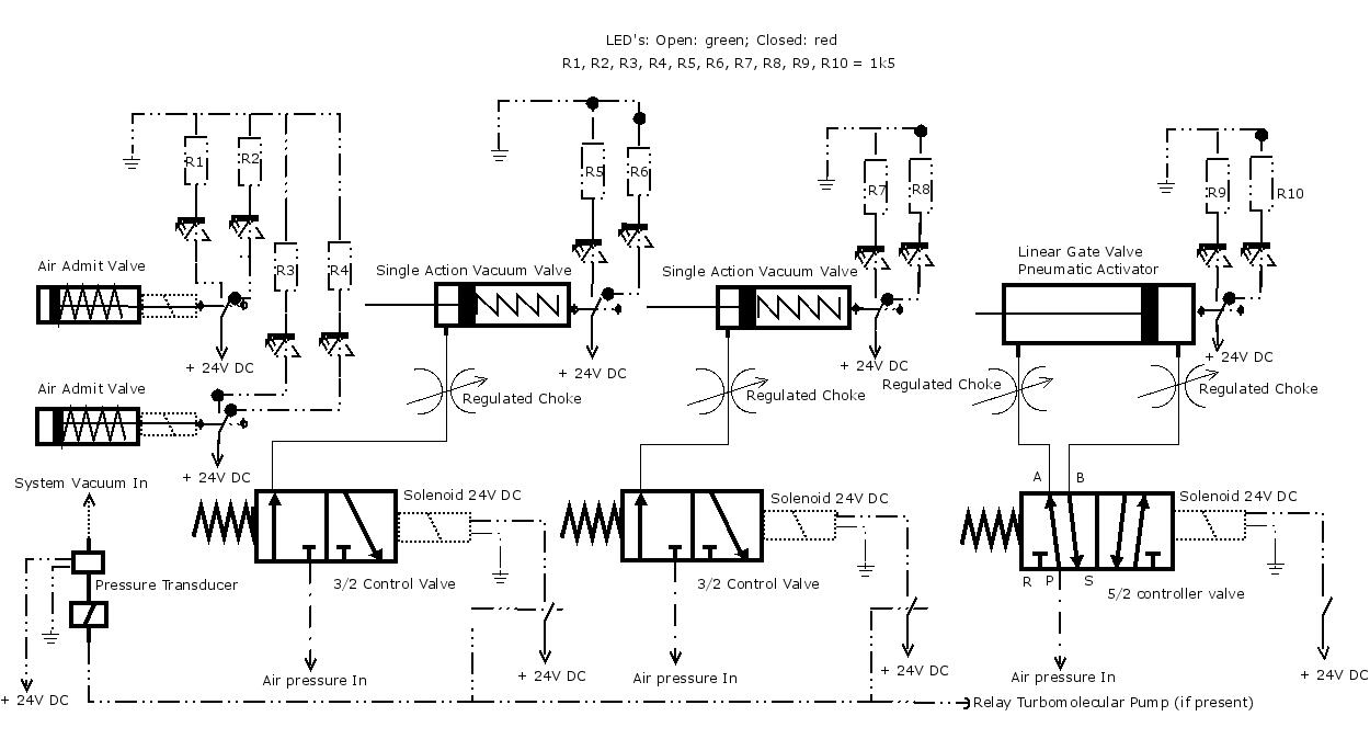 Image 64: Combined
pneumatic control system and 24 V DC system (© FRS 2015)
The two single action valves and the butterfly valve have microswitches in the valve body, which are closed or opened depending on the position of the valve. Green and red LED's indicate the opened or closed postion of these valves, yielding real time information about the valve status. The two air admit valves do not have microswitches and instead it is only monitored whether the solenoid is under power or not, which is an indirect way of signalling the status of these valves. Our initial intention to operate all vacuum valves with manual switches was abandonned when the Baratron vacuum pressure switch and the turbo drag hybrid pump were acquired. The switch offered the possibility to control the vacuum system and to start an action when the pressure dropped unexpectedly; the turbo drag hybrid pump required venting when such an unexpected situation occurred. Therefore the manual switches had to be replaced by impuls switches or latching relays, which permit electronic overruling of the chosen vacuum pump setting (i.e. open or closed). More about the vent control system can be found on the controls systems page. ≈
|
|||||||||||||||||||||||||||||||||||||||||||||||||||||||||||||||||||||||||||||||||||||||||||||||||||||||||||||||||||||||||||||||||||||||||||||||||||||||||
 |
 |
 |
 |
 |
 |
 |
 |
 |
 |
 |
Last Updated on: Fri Aug 4 13:17:41 2017 |